Troubleshooting Energy Minimization in MD Simulations: A Comprehensive Guide for Biomedical Researchers
This article provides a comprehensive framework for understanding and resolving common energy minimization failures in Molecular Dynamics (MD) simulations, a critical step in computational drug discovery and biomolecular modeling.
Troubleshooting Energy Minimization in MD Simulations: A Comprehensive Guide for Biomedical Researchers
Abstract
This article provides a comprehensive framework for understanding and resolving common energy minimization failures in Molecular Dynamics (MD) simulations, a critical step in computational drug discovery and biomolecular modeling. We first establish the foundational principles of energy minimization and its role in achieving a stable system configuration. The guide then details practical methodologies, including the selection and application of minimization algorithms like Steepest Descent and Conjugate Gradient. A core focus is a systematic troubleshooting protocol for diagnosing and fixing convergence errors, high forces, and instability, supported by real-world case studies. Finally, we cover validation techniques to confirm minimization success and ensure the reliability of simulation results for downstream biomedical applications.
Understanding Energy Minimization: The Bedrock of Stable MD Simulations
Defining Energy Minimization and Its Critical Role in the MD Pipeline
Energy minimization is a foundational step in Molecular Dynamics (MD) simulations. Its primary role is to reduce the potential energy of a molecular system to a local minimum, resolving any unrealistic atomic clashes, strained bond angles, or torsions that may be present in the initial configuration, such as one derived from experimental coordinates [1]. This process is critical because initiating a dynamics simulation from a high-energy state can lead to numerical instabilities, simulation crashes, or the propagation of unrealistic structural artifacts. A properly minimized structure provides a stable and physically meaningful starting point for subsequent MD simulation steps.
Frequently Asked Questions (FAQs)
1. Why did my energy minimization fail to converge? Failure to converge often occurs when the initial structure is highly distorted, leading to extremely high initial forces. This can be addressed by starting with the steepest descent algorithm for the first 10-100 steps before switching to a more efficient method like conjugate gradients [1]. Additionally, check for atomistic clashes in your initial model and ensure your convergence criteria (e.g., maximum force) are not set too stringently for the system's initial state.
2. How do I choose the right minimization algorithm? The choice depends on your system's size and its current state of optimization [2] [3] [1].
- Steepest Descent: Robust and best for the initial stages of minimization when the structure is far from a minimum and forces are high. It is less efficient closer to the minimum.
- Conjugate Gradients: More efficient than steepest descent as the system approaches a minimum. It is the method of choice for systems too large for Newton-style minimizers. Note that it cannot be used with constraints in some software [3].
- L-BFGS: A quasi-Newtonian method that often converges faster than conjugate gradients. However, it may not yet be parallelized in some MD software [3].
3. What is a reasonable convergence criterion for my simulation? The required convergence threshold depends on the objective of your minimization [1].
- Pre-dynamics relaxation: A maximum force of
1.0 kcal mol⁻¹ Å⁻¹is often sufficient. - Normal mode analysis: Requires a very high degree of convergence, with a maximum force below
10⁻⁵ kcal mol⁻¹ Å⁻¹.
4. When should I use constraints or restraints during minimization? Constraints and restraints are useful for controlling the minimization process [1].
- Docking studies: To pull specific atoms (e.g., a donor and acceptor) together to form a hydrogen bond.
- Incomplete systems: To tether atoms in regions where parts of the model are missing (e.g., unresolved loops in a protein crystal structure) to prevent artifactual movement.
- Relaxing crystal structures: A multi-stage approach where heavy atoms are fixed to relax hydrogens first, followed by side chains, and finally the entire backbone, to gently relax the system without moving away from the experimental structure.
Troubleshooting Guide
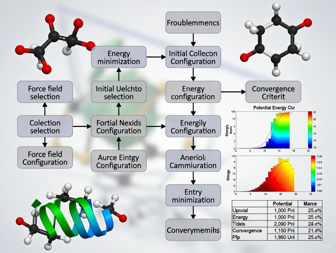
The following flowchart outlines a logical procedure for diagnosing and resolving common energy minimization failures.
★ Key Algorithm Comparison
Table: Comparison of Common Energy Minimization Algorithms in MD
| Algorithm | Typical Use Case | Advantages | Limitations | Key Parameters |
|---|---|---|---|---|
| Steepest Descent [3] [1] | Initial minimization; highly distorted structures | Robust, stable when far from minimum | Slow convergence near minimum; inefficient | emstep (max displacement), nsteps |
| Conjugate Gradient [2] [3] | Intermediate to final minimization stages | More efficient than steepest descent near minimum | May not be compatible with all constraints [3] | emtol (force tolerance), nsteps |
| L-BFGS [2] [3] | Final minimization stages | Fast convergence; low memory requirements | Not fully parallelized in some software [3] | emtol (force tolerance), nsteps |
Experimental Protocols
Standard Protocol for Relaxing a Crystal Structure
This protocol is essential for preparing experimentally derived structures for MD simulation, as it gently relieves steric clashes without causing large, artifactual movements away from the native state [1].
Minimize added atoms with fixed heavy atoms
- Objective: Allow added hydrogens and solvent molecules to adjust to the static protein environment.
- Method: Fix the coordinates of all non-hydrogen atoms. Use the steepest descent algorithm.
- Convergence: Stop when the energy derivatives are on the order of ~10 kcal mol⁻¹ Å⁻¹ [1].
Minimize side chains with restrained backbone
- Objective: Relax the side chains, particularly those on the surface.
- Method: Apply positional restraints to the main chain (backbone) atoms while allowing side chains to move freely. Steepest descent is recommended initially.
- Convergence: Continue until derivatives are less than ~10 kcal mol⁻¹ Å⁻¹.
Gradually relax the entire system
- Objective: Achieve a fully relaxed, unperturbed conformation.
- Method: Progressively reduce the force constant of the positional restraints on the backbone atoms until they can be completely removed. Switch from steepest descent to conjugate gradients or L-BFGS for final convergence [1].
The Scientist's Toolkit: Essential "Research Reagent Solutions"
Table: Key Software Parameters and Components for Energy Minimization
| Item / Reagent | Function / Description | Typical Settings / Examples |
|---|---|---|
| Integrator (mdp option) [2] | Specifies the minimization algorithm. | steep (steepest descent), cg (conjugate gradient), l-bfgs |
Force Tolerance (emtol) [3] |
Defines the convergence criterion based on the maximum force. | 1.0-1000 kJ mol⁻¹ nm⁻¹ for pre-dynamics; much lower for normal modes. |
Maximum Steps (nsteps) [2] |
Sets the maximum number of minimization steps allowed. | -1 (no limit) or a fixed number (e.g., 1000). |
| Constraints [1] | Used to freeze or tether specific atoms during minimization to guide the process. | Positional restraints on protein backbone during initial stages. |
| Simple Forcefield [1] | A forcefield without cross terms or complex potentials; improves stability for highly distorted structures. | Using a forcefield with simple quadratic functional forms. |
FAQ: What are the fundamental components of a potential energy function in molecular dynamics?
The total potential energy (V) of a molecular system in a molecular dynamics (MD) simulation is typically calculated as the sum of bonded and non-bonded interaction energies [4] [5]. This is formally expressed with the equation:
V = Vbonded + Vnon-bonded
The bonded interactions describe the energy associated with the covalent chemical structure, while the non-bonded interactions describe the energy from forces between atoms that are not directly bonded [4]. This separation allows force fields to efficiently model the complex energetics of biological macromolecules.
FAQ: What specific terms constitute the bonded interactions?
The bonded energy term is itself a sum of several components, each governing a specific aspect of the molecular geometry [4] [5]. The table below summarizes these core bonded interactions.
Table 1: Core Bonded Interaction Energy Terms
| Term | Mathematical Form | Description | Governs |
|---|---|---|---|
| Bond Stretch | ( \sum{bonds} Kb(b - b_0)^2 ) | Energy required to stretch or compress a covalent bond from its ideal length, ( b_0 ). | Bond lengths |
| Angle Bend | ( \sum{angles} K{\theta}(\theta - \theta_0)^2 ) | Energy required to bend the angle between two adjacent bonds from its ideal value, ( \theta_0 ). | Bond angles |
| Torsional Dihedral | ( \sum{dihedrals} [K{\phi}(1 + cos(n\phi - \delta))] ) | Energy associated with rotation around a central bond, defined by periodicity (n), phase (δ), and force constant (Kφ). | Dihedral angles |
| Improper Dihedral | ( \sum{impropers} K{\omega}(\omega - \omega_0)^2 ) | Energy used to maintain chirality at a central atom or to enforce planarity in groups like aromatic rings. | Out-of-plane bending |
FAQ: What are the non-bonded interactions and why are they critical?
The non-bonded interactions act between atoms that are not connected by covalent bonds, and they are crucial for determining the tertiary structure of proteins, binding affinity of ligands, and solvent-solute interactions [4] [6] [5]. They are primarily composed of two terms:
Table 2: Core Non-Bonded Interaction Energy Terms
| Term | Mathematical Form | Physical Origin |
|---|---|---|
| van der Waals | ( \sum{VDW} \left[ \left( \frac{A{ij}}{R{ij}^{12}} \right) - \left( \frac{B{ij}}{R_{ij}^{6}} \right) \right] ) | Models short-range repulsive and attractive (dispersion) forces due to fluctuating electron clouds. Often represented with a Lennard-Jones potential. |
| Electrostatic | ( \sum{Electrostatic} \frac{qi qj}{\epsilon R{ij}} ) | Models the long-range Coulombic interaction between partial or full atomic charges (qi, qj). |
A common combination rule for the van der Waals parameters between two different atoms i and j is: ( A{ij} = \sqrt{Ai Aj} ) and ( B{ij} = \sqrt{Bi Bj} ) [4]. A weighting function is typically applied to exclude non-bonded interactions for atoms directly connected by a bond or angle, and to scale them for atoms connected through three bonds (1-4 interactions) [4].
Troubleshooting Guide: My energy minimization fails with high forces and non-convergence. What should I do?
Energy minimization failure is a common issue where the algorithm cannot reduce the maximum force (Fmax) below a requested threshold. This often manifests with error messages about high forces on specific atoms [7] [8]. The following workflow provides a systematic diagnostic approach.
Diagnosis and Solutions
Symptom: Minimization stops with a very high Fmax (e.g., > 10,000 kJ/mol/nm) on a specific atom, often reported in the .log file [7] [9] [8].
Symptom: Bad contacts or atomic clashes are found upon visualization [9].
- Action: The initial molecular geometry may be physically unrealistic, often resulting from automated structure preparation or docking. Manually edit the initial coordinate file to resolve severe clashes before re-running minimization.
Symptom: The high-force atoms are located at the edge of the simulation box, potentially in a periodic system like a zeolite or a crystal [9].
- Action: This suggests missing covalent bonds across the periodic boundary. The topology file must explicitly list all bonds, including those that connect a unit cell to its periodic image. Check the
[ bonds ]section of your topology. For some systems, settingperiodic-molecules = yesin your .mdp file may be necessary, though this does not automatically create the bonds [9].
- Action: This suggests missing covalent bonds across the periodic boundary. The topology file must explicitly list all bonds, including those that connect a unit cell to its periodic image. Check the
Symptom: The problem occurs with a non-standard molecule like a drug ligand.
- Action: Incorrect parametrization of the ligand is a likely cause. Re-check the process used to generate the ligand's topology and parameters, paying close attention to partial atomic charges, bond types, and the assignment of atom types.
Troubleshooting Guide: Are there limitations to what energy minimization can achieve?
Yes, energy minimization has fundamental limitations that every researcher must understand. Minimization finds a local minimum on the potential energy surface, which is highly dependent on the starting configuration [10]. It does not account for thermal fluctuations or entropic effects, which are critical for understanding biological function and selectivity at physiological temperatures [10].
- Pitfall: Relying on a single minimized structure to calculate properties like ion selectivity can lead to erroneous and misleading conclusions, as the energy difference between different local minima can be large and unpredictable [10].
- Best Practice: For properties related to binding, stability, or selectivity, always follow minimization with molecular dynamics simulations to perform proper thermodynamic averaging over an ensemble of configurations [10].
The Scientist's Toolkit: Essential Reagents for Energy Minimization
Table 3: Key Research Reagents and Computational Tools
| Item / Software | Function in Energy Minimization |
|---|---|
| MD Engine (e.g., GROMACS, CHARMM, AMBER) | Executes the minimization algorithm, calculates energy/forces, and integrates the equations of motion. |
| Molecular Visualization Tool (e.g., VMD, PyMOL) | Critical for diagnosing errors by visually inspecting atomic clashes and the environment around high-force atoms. |
| Force Field (e.g., CHARMM, AMBER, OPLS) | Provides the parameters (Kb, b0, q, Aij, Bij) for the potential energy function. |
| Steepest Descents Algorithm | A robust minimization algorithm often used for the initial steps to relieve severe clashes from poor starting structures. |
| Conjugate Gradient Algorithm | A more efficient minimization algorithm typically used after steepest descents for finer convergence. |
| Position Restraints | A computational tool (harmonic potential) applied to atom positions to allow solvent/lipids to relax around a fixed protein scaffold. |
Fundamental Concepts: The Potential Energy Surface
What is a Potential Energy Surface (PES)?
A Potential Energy Surface (PES) describes the energy of a collection of atoms as a function of their nuclear positions [11]. Conceptually, it represents an "energy landscape" where the height corresponds to energy and the geographical coordinates correspond to geometrical parameters of the molecular system [11]. The PES is obtained by solving the time-independent Schrödinger equation under the Born-Oppenheimer approximation, which separates nuclear and electronic motion because electrons move much faster than nuclei [12].
What are stationary points and why are they important?
Stationary points are specific geometries on the PES where the energy gradient (first derivative) with respect to all nuclear coordinates is zero [12] [11]. They have profound physical significance:
- Energy Minima: Correspond to physically stable chemical species [11]. These can be:
- Saddle Points: Transition states that represent the highest energy point on the lowest energy pathway connecting two minima [11].
Key Challenges in Energy Minimization
Why is finding the global minimum so difficult?
Finding the global minimum on a PES is classified as an NP-hard problem, meaning its complexity grows exponentially with system size [13]. Key challenges include:
- Rugged Landscapes: PES for molecular systems typically contain enormous numbers of local minima. For example, a 13-atom cluster system can have over 12,000 minima and 54,000 transition states [13].
- Short-Ranged Potentials: Potentials with shorter interaction ranges create more rugged landscapes with higher barriers and more localized rearrangements, making escape from local minima more difficult [13].
- Structural Similarity: Pathways to certain minima (e.g., decahedral structures) may be fewer and longer than to others (e.g., icosahedral structures), creating "hard-to-reach" regions on the PES [13].
What common computational errors occur during geometry optimization?
Table 1: Common Geometry Optimization Errors and Solutions
| Error Message | Possible Causes | Troubleshooting Steps |
|---|---|---|
| "Stepsize too small, or no change in energy. Converged to machine precision, but not to the requested Fmax" [14] | Energy minimization limit reached; High water content systems | Interpret Fmax value; Consider double precision; Different minimization methods [14] |
| "Energy minimization has stopped because the force on at least one atom is not finite" [14] | Atoms too close in input coordinates | Check initial coordinates; Use soft-core potentials [14] |
| "Cannot do Conjugate Gradients with constraints" [14] | Algorithm incompatibility with constraints | Use alternative algorithms that support constraints [14] |
| Discontinuities in force evaluation [15] | Bond order cutoff issues in ReaxFF | Decrease BondOrderCutoff; Use 2013 torsion angles; Enable TaperBO [15] |
Methodologies and Algorithms
What algorithms are used for geometry optimization?
Table 2: Energy Minimization Algorithms Comparison
| Algorithm | Mechanism | Advantages | Limitations |
|---|---|---|---|
| Steepest Descent [3] | Moves atoms opposite to energy gradient direction | Robust, easy to implement; Good for initial optimization steps | Slow convergence near minimum; Inefficient for complex landscapes |
| Conjugate Gradient [3] | Uses conjugate direction vectors for search | More efficient closer to energy minimum; Faster convergence than steepest descent | Cannot be used with constraints in some implementations [14] |
| L-BFGS [3] | Quasi-Newton method approximating inverse Hessian | Fast convergence; Lower memory requirements than full BFGS | Not yet parallelized in some implementations; Sensitive to interaction cutoffs |
What global optimization strategies effectively explore the PES?
- Physical Insight Construction: Building structures that maximize favorable interactions (e.g., maximizing nearest-neighbor contacts for clusters) followed by local minimization [13].
- Molecular Dynamics Sampling: Using high-energy runs to sample large PES regions and low-energy runs for detailed local searching [13].
- Basin Hopping Techniques: Using eigenvector-following to step directly between minima combined with Monte Carlo sampling to walk down basins containing multiple minima [13].
Experimental Protocols
Standard Geometry Optimization Protocol
- Initial Structure Preparation: Create or obtain starting structure from databases or publications [12].
- Coordinate System Selection: Convert Cartesian coordinates to internal coordinates to eliminate translational and rotational degrees of freedom ($3N-6$ internal coordinates for $N$ atoms) [12].
- Algorithm Selection:
- Convergence Monitoring: Iteratively calculate energy gradients and displace atoms until maximum force components fall below threshold (typically 1-10 kJ mol$^{-1}$ nm$^{-1}$) [3].
- Result Validation: Confirm optimized geometry corresponds to a minimum (not a saddle point) through frequency analysis.
Troubleshooting Failed Optimizations
- For discontinuous forces: In ReaxFF, decrease
BondOrderCutoffor enableTaperBOto smooth energy derivatives [15]. - For constrained systems: Avoid conjugate gradients; use steepest descent or specialized constraint algorithms [14].
- For system instability: Ensure thorough energy minimization and equilibration before dynamics runs; validate topology parameters [14].
Essential Research Tools
Visualization of PES Navigation Strategies
Frequently Asked Questions
How can I distinguish between a local minimum and the global minimum?
There is no guaranteed method to prove a structure is the global minimum for complex systems [13]. Effective approaches include:
- Using multiple diverse starting structures for optimization
- Applying different global optimization algorithms
- Comparing energies of all found minima
- For clusters, known structural motifs (icosahedral, decahedral, fcc) provide candidate templates [13]
Why do my optimizations converge slowly or oscillate?
Slow convergence may result from:
- Inappropriate step sizes: The algorithm takes steps that are too large (causing oscillation) or too small (slow progress) [3]
- Rugged PES topography: The energy landscape has many closely spaced minima [13]
- Discontinuous forces: Sudden changes in force evaluation, common with bond order cutoffs in reactive force fields [15]
What is the relationship between PES features and chemical reactivity?
- Attractive (early-downhill) PES: Transition state resembles reactants; product energy released primarily as vibrational energy [11]
- Repulsive (late-downhill) PES: Transition state resembles products; energy released primarily as translational energy [11]
- For endothermic reactions, translational energy is most effective for attractive surfaces while vibrational excitation works better for repulsive surfaces [11]
When is a structure "sufficiently optimized" for further calculations?
A structure is sufficiently optimized when:
- Maximum force components are below a reasonable threshold (1-10 kJ mol$^{-1}$ nm$^{-1}$ depending on system and purpose) [3]
- Further optimization does not significantly change the energy or structure
- The resulting geometry has physically reasonable bond lengths and angles
- For subsequent property calculations, ensure the geometry represents a minimum, not a transition state [12]
FAQs: Troubleshooting Energy Minimization
My energy minimization fails with "the forces have not converged" or "Fmax is too high". What does this mean?
This common error indicates that the energy minimization algorithm stopped before the forces in your system were reduced to an acceptable level. The following table summarizes the core aspects of this problem and its solutions.
Table: Troubleshooting "Forces Not Converged" Errors
| Error Symptom | Likely Cause | Immediate Action | Long-term Solution |
|---|---|---|---|
High Fmax and Epot after max steps [7] |
Atom overlaps: Atoms are too close, creating infinite repulsive forces [16]. | Check atom 2089 (or the reported atom) for clashes, especially in ligands [7] [16]. | Visually inspect structure; use -ignore flag in pdb2gmx sparingly; ensure correct protonation states [17]. |
Fmax = inf (infinite force) [16] |
Severe atomic clashes: Critical overlaps in the initial structure [16]. | Inspect and correct the coordinates of the offending atom (e.g., atom 1251) [16]. | Verify ligand topology matches coordinate file; correct any atom name mismatches [16]. |
Convergence to machine precision, but Fmax still high [7] |
Local energy minimum: Minimizer is "stuck" and cannot find a lower energy path [7]. | Switch from steepest descent to conjugate gradient minimizer. | Increase the maximum number of steps (nsteps) or try a two-step minimization protocol. |
Detailed Methodology for Resolution:
- Identify the Problem Atom: The log file specifies the atom with the maximum force (e.g.,
atom= 2089). Note this number [7]. - Visual Inspection: Use a molecular visualization tool (e.g., PyMOL, VMD) to center your view on this specific atom. Look for unrealistic bond lengths or atoms occupying the same space, particularly in newly added ligands or solvent molecules [16].
- Correct the Topology: A frequent cause for ligands is a mismatch between the atom names or coordinates in the structure file (
.gro/.pdb) and the topology file (.top). Ensure they are consistent [16]. - Adjust Minimization Parameters: If no severe clashes are found, the system may be trapped. Modify your
em.mdpfile:- Increase
nsteps = 100000to allow more minimization steps. - Change the integrator to
integrator = cg(conjugate gradients), which can be more effective for certain systems. - As a last resort for severe clashes, consider using soft-core potentials as suggested in the error message [16].
- Increase
I get an "Atom index in position_restraints out of bounds" error. How do I fix it?
This error occurs when the atom indices in your position restraint file (posre.itp) do not match the actual atom order in your system. This is almost always caused by an incorrect ordering of #include statements in your master topology file (topol.top).
Detailed Methodology for Correction:
The solution is to ensure that the position restraints for a molecule are included immediately after the topology for that same molecule. The correct structure for your topol.top file is [17]:
The following workflow illustrates the correct and incorrect ways to include position restraints when building your system.
Correct vs. Incorrect Position Restraint Inclusion
What should I do if pdb2gmx fails with "Residue not found in topology database"?
This error means the force field you selected does not have a definition for a specific residue or molecule in your input structure file [17].
Detailed Methodology for Handling Unparameterized Residues:
- Check Residue Name: Verify the residue name in your
.pdbfile matches the expected name in the force field. For example, an N-terminal alanine in the AMBER force field should be namedNALA, notALA[17]. - Find an Existing Topology: Search online repositories for a pre-made topology file (
.itp) for your molecule that is compatible with your chosen force field. - Parameterize the Residue Yourself: If no topology exists, you must create one. This involves:
- Creating an RTP Entry: Define the residue's atoms, bonds, and angles in a Residue Topology Parameter (RTP) file for your force field [17].
- Deriving Parameters: Assign non-bonded parameters (atom types) and bonded parameters (bond, angle, dihedral force constants). This often requires ab initio quantum mechanics calculations and is a non-trivial task [17].
- Use a Different Tool: For non-standard molecules like drugs, consider using specialized tools like
x2topor web-based servers (e.g., CGenFF, ATB, PRODRG) to generate the initial topology, which you can then include in your system [17].
My minimization stops with "atoms are overlapping". How can I resolve this?
This is a specific and severe instance of a convergence failure, where the force on an atom becomes infinite due to a physical impossibility in the structure [16].
Detailed Methodology for Resolving Atomic Overlaps:
- Locate the Overlap: The error log will specify the atom number with infinite force (e.g.,
atom= 1251). Use visualization software to find this atom [16]. - Inspect the Local Environment: Check if this atom is unnaturally close to or inside another atom. This is common in manually built or modified structures, and particularly for ligands that were not properly energy-minimized before insertion [16].
- Correct the Structure:
- Manual Adjustment: In your visualization program, manually move the offending atom or its neighbor to a chemically reasonable position.
- External Minimization: Perform a preliminary energy minimization on the problematic molecule (e.g., your ligand) in a vacuum using a molecular modeling suite like MOE or Avogadro before inserting it into the larger system [16].
- Check Topology-Structure Consistency: Ensure the ligand's topology and coordinate file are consistent. Mismatches here can create perceived "overlaps" where the topology expects different atom names or connectivities [16].
The Scientist's Toolkit: Essential Research Reagents and Software
Table: Key Tools for MD System Setup and Minimization
| Tool Name | Function | Key Usage Notes |
|---|---|---|
pdb2gmx |
Generates topology and position restraints for proteins/nucleic acids from a PDB file [17]. | Selects the force field; cannot handle arbitrary organic molecules without a defined residue template [17]. |
grompp |
Assembles the molecular dynamics parameter (.mdp) file, topology, and coordinates into a portable binary (.tpr) for simulation [17]. |
Checks for parameter consistency; warnings should be reviewed carefully [17]. |
mdrun |
The main simulation engine that executes energy minimization and production MD [7] [16]. | Use the -v (verbose) and -deffnm (default filename) flags for clearer logging [7]. |
solvate |
Adds explicit solvent molecules (e.g., water) to the simulation box around the solute [17] [18]. | Ensure the box size provides sufficient padding (>1.0 nm) from the solute to prevent artifacts [18]. |
genion |
Replaces solvent molecules with ions to neutralize the system's charge or achieve a physiological concentration [18]. | Ions are placed based on the electrostatic potential; check the final ion distribution for realism [18]. |
| Molecular Viewer (VMD/PyMOL) | Visualizes structures, checks for errors, and analyzes trajectories post-simulation [18]. | Critical for inspecting atoms flagged in error messages and verifying system integrity [16]. |
Experimental Protocol: A Standard Energy Minimization Workflow
The following diagram outlines a robust workflow for system setup and energy minimization, incorporating checks to prevent common errors.
Energy Minimization and Error Checking Workflow
Troubleshooting Guides
FAQ: Diagnosing and Resolving High-Energy Issues
1. How can I identify a steric clash in my structure, and what is the best way to resolve it?
Steric clashes occur when atoms are positioned unrealistically close together, resulting in a sharp, localized spike in potential energy due to strong van der Waals repulsion.
- Diagnosis: Visualize your structure using molecular visualization software (e.g., PyMOL, VMD) and enable the display of van der Waals radii. Look for atoms whose radii significantly overlap. Energetically, this will manifest as a very high contribution from the Lennard-Jones term in your energy output.
- Resolution: The most direct method is to perform energy minimization before beginning your production simulation. This allows the atoms to "relax" into a geometry that relieves the clash. For severe clashes, consider rebuilding the problematic region or checking the initial model construction.
2. My simulation has unrealistic bond lengths or angles. What causes "bad dihedrals" and how do I fix them?
In molecular mechanics, "bad dihedrals" typically refer to incorrect torsional angles that place the molecule in a high-energy conformation not supported by quantum mechanical data [19]. This can lead to inaccurate conformational distributions.
- Diagnosis: Analyze the torsional energy profiles of your molecule. Compare the energy barriers and stable states predicted by your force field against higher-level quantum mechanical (QM) calculations. Large discrepancies indicate problematic dihedral parameters [19].
- Resolution:
- Refit Parameters: For a custom molecule, the best practice is to refit the dihedral parameters to QM torsion scans [19] [20]. This involves running QM calculations to map the energy as a function of the dihedral angle and then optimizing the force field parameters to reproduce this profile.
- Use a Modern Force Field: Consider using a machine-learned force field like Grappa or ByteFF, which use neural networks to predict more accurate parameters directly from the molecular graph, often leading to better dihedral profiles [19] [21].
3. Why does my molecule have high energy in solvent, and how can I address solvent conflicts?
Solvent conflicts, or poor solvation, arise when a molecule's polarity and surface characteristics are mismatched with its solvent environment. This is a major driver of errors in free energy calculations [22] [23].
- Diagnosis: High non-bonded energy (electrostatic and van der Waals) between the solute and solvent is a key indicator. Experimentally, this might be reflected in large errors when calculating solvation free energies [22].
- Resolution:
- Check Partial Charges: Ensure the partial charges on your small molecule are accurately derived, for example, from a QM-calculated electrostatic potential (ESP). Using fixed charges that don't account for polarization in the binding site can significantly impact accuracy [23].
- Validate with Solvation Free Energy: Use alchemical free energy calculations to compute the solvation free energy of your molecule and compare it to experimental values. A large error suggests issues with the non-bonded parameters [22].
- Advanced Methods: For the highest accuracy, protocols that combine QM/MM calculations to derive context-dependent charges for the ligand have been shown to significantly improve binding free energy estimates [23].
4. What are the best practices for setting up a system to avoid common energy issues?
A proper system setup is the first line of defense against high-energy states.
- Use a Validated Force Field: Select a force field appropriate for your system (e.g., AMBER, CHARMM, OPLS). For drug-like molecules, modern, data-driven force fields like ByteFF offer broad chemical space coverage [19].
- Solvate Correctly: Place your molecule in a sufficiently large box of explicit solvent molecules (e.g., TIP3P water) and add ions to neutralize the system's total charge [24].
- Apply Periodic Boundary Conditions (PBC): Use PBC to simulate a bulk solution environment and avoid edge effects. Be aware that molecules will freely diffuse across the box boundaries, which is normal but must be handled correctly for analysis [25].
- Always Perform Minimization: Before heating and equilibration, always run an energy minimization step to relieve any steric clashes introduced during system building.
Quantitative Data and Protocols
Table 1: Characteristic Signs of Common High-Energy Problems
| Issue | Primary Energy Component Affected | Structural Signature | Computational Diagnostic |
|---|---|---|---|
| Steric Clashes | Lennard-Jones (van der Waals repulsion) | Overlapping van der Waals radii [24] | High individual interatomic forces; failed energy minimization |
| Bad Dihedrals | Torsional Energy | Incorrect rotational state around bonds [19] | Large deviation from QM torsion energy profiles [19] |
| Solvent Conflicts | Non-bonded (Electrostatics & Lennard-Jones) | Poor interaction with solvent shell; incorrect binding pose | Large errors in solvation or binding free energy calculations [22] [23] |
| Issue | Standard Resolution | Advanced/Data-Driven Resolution |
|---|---|---|
| Steric Clashes | Energy Minimization | - |
| Bad Dihedrals | Manual refitting to QM torsion scans [19] [20] | Machine-learned force fields (e.g., Grappa, ByteFF) [19] [21] |
| Solvent Conflicts | Reparametrization of partial charges | QM/MM-derived charges; ML-potentials in alchemical protocols [22] [23] |
Experimental Protocol: QM/MM Charge Derivation for Improved Solvation
This protocol outlines the method for deriving improved partial charges for a ligand in a protein binding pocket to address solvent/solvation conflicts, as used in high-accuracy binding free energy estimation [23].
- Generate Initial Pose: Use a classical method (e.g., docking, MM minimization) to generate a likely binding pose for the ligand-protein complex.
- Define QM and MM Regions: Set up a QM/MM calculation where the ligand is the QM region (treated with quantum mechanics) and the protein and solvent are the MM region (treated with the molecular mechanics force field).
- Calculate Electrostatic Potential (ESP): Perform a QM calculation on the QM region in the presence of the MM environment to compute the electrostatic potential around the ligand.
- Fit Partial Charges: Fit the partial charges of the ligand's atoms so that they reproduce the QM-derived ESP. This results in charges that are polarized by the protein environment.
- Run Free Energy Calculations: Use these new QM/MM-derived charges in subsequent free energy calculations (e.g., using the Mining Minima method or alchemical perturbation) [23].
Workflow Diagrams
Diagram: Troubleshooting High Energy in MD Simulations
The Scientist's Toolkit
Research Reagent Solutions
| Item | Function in Troubleshooting |
|---|---|
| Graph Neural Networks (GNNs) | Used in modern force fields like Grappa and ByteFF to predict more accurate molecular mechanics parameters (bonds, angles, dihedrals) directly from a molecule's structure, mitigating bad dihedrals [19] [21]. |
| Alchemical Free Energy Calculations | A rigorous thermodynamic method used to compute free energy differences (e.g., solvation free energy, binding free energy). It is a key diagnostic for validating non-bonded parameters and identifying solvent conflicts [22]. |
| QM/MM (Quantum Mechanics/Molecular Mechanics) | A hybrid method where a small, critical region (e.g., a ligand) is treated with accurate QM, and the surroundings are treated with MM. Used to generate polarized partial charges for ligands, improving the treatment of electrostatics and solvation [23]. |
| Beutler-type Soft Core Potentials | A modified potential energy function used in alchemical calculations to prevent numerical singularities when atoms are "created" or "annihilated," ensuring smooth and convergent free energy estimates [22]. |
A Practical Guide to Minimization Algorithms and Their Implementation
Energy minimization is a critical first step in Molecular Dynamics (MD) simulations, aimed at reaching the nearest local minimum of the potential energy surface by reducing excessive forces and relieving steric clashes in the initial molecular configuration [26]. The choice of minimization algorithm directly impacts the stability of your simulation, the time to solution, and the quality of your final results. Within the context of a broader thesis on troubleshooting MD research, this guide provides a technical comparison and practical troubleshooting for three core algorithms: the robust Steepest Descent, the more efficient Conjugate Gradient, and the advanced L-BFGS.
This technical support center is designed to help you diagnose common issues, understand the trade-offs between different methods, and implement effective solutions to ensure your energy minimization converges to a stable configuration.
Algorithm Comparison Table
The table below summarizes the key characteristics of the three main energy minimization algorithms to help you make an informed choice.
Table 1: Comparative Overview of Energy Minimization Algorithms
| Feature | Steepest Descent | Conjugate Gradient | L-BFGS |
|---|---|---|---|
| Core Principle | Moves in the direction of the negative gradient (steepest force) [27]. | Uses conjugate directions to avoid re-visiting previous minimization paths [28]. | Approximates the inverse Hessian matrix using a history of updates [3]. |
| Convergence Speed | Linear convergence rate; can be slow [27]. | Faster than Steepest Descent near the minimum [3]. | Faster than Conjugate Gradients [3]. |
| Memory Requirements | Low | Low | Moderate (proportional to system size and correction steps) [3]. |
| Robustness | High; excellent for initial steps and poorly-structured systems [3]. | High, but cannot be used with all constraints (e.g., SETTLE for water) [3]. | High, but performance can be affected by switched/shifted interactions [3]. |
| Best Use Case | Initial minimization of structures with high energy and clashes [3]. | Minimization prior to normal-mode analysis or when higher accuracy is needed [3]. | Efficient minimization for large systems like biomolecules [3]. |
| Key Limitation | "Zigzag" phenomenon slows convergence in ill-conditioned problems [27]. | Not compatible with constraints like SETTLE water [3]. | Not yet fully parallelized in some implementations (e.g., GROMACS) [3]. |
Frequently Asked Questions (FAQs) and Troubleshooting
FAQ 1: My energy minimization stops abruptly, reporting that "forces have not converged." What should I do?
This is a common issue where the algorithm halts because it can no longer make progress, even though the target force tolerance (Fmax) has not been met. The system is deemed converged to the best of its ability given the starting configuration and parameters [29] [30].
Troubleshooting Steps:
- Check for Steric Clashes: A very high potential energy or maximum force often indicates severe atomic clashes in your initial structure [30]. Visualize the system, paying close attention to the atoms listed in the error output (e.g.,
Maximum force = 7.0742570e+04 on atom 1447) [29]. - Verify Position Restraints: Ensure you are not accidentally using position restraints (e.g.,
define = -DPOSRESin your MDP file) that might be preventing the system from relaxing [30]. - Adjust Minimization Parameters:
- Switch Algorithms: If Steepest Descent gets stuck, it is often recommended to use its output as the starting point for a more efficient algorithm like Conjugate Gradient or L-BFGS [29] [3].
FAQ 2: How do I choose between Steepest Descent and Conjugate Gradient for my protein-in-water system?
The choice involves a trade-off between robustness and final accuracy.
- Use Steepest Descent when you need a robust method to quickly relieve severe clashes and bring a poorly-structured system to a lower energy state. Its simplicity makes it reliable for the initial, rough minimization [3].
- Use Conjugate Gradient when your system is already reasonably well-structured and you require a more accurate minimization for subsequent analysis. It is more efficient than Steepest Descent closer to the energy minimum [3].
Critical Constraint Note: If your system uses the SETTLE algorithm for water (which is standard for rigid water models like SPC, TIP3P, etc.), you cannot use Conjugate Gradient. In this case, you must either use Steepest Descent or switch to a flexible water model [3].
FAQ 3: What does a "Segmentation fault" during minimization indicate, and how can I resolve it?
A segmentation fault is a serious error indicating the program tried to access memory it was not permitted to, leading to a crash [29]. This is often unrelated to the choice of algorithm itself and points to a deeper problem.
Potential Causes and Solutions:
- Software or Hardware Issue: A faulty installation of GROMACS, incompatible libraries, or hardware problems can cause this.
- System Corruption: The structure of your system may be corrupted or contain invalid parameters that trigger an error during force calculation.
- GPU Acceleration Issues: If running on a GPU, try running on CPU only (
-nb cpu -pme cpu) to rule out GPU-related issues. - Check Your Topology: Carefully inspect your topology file (
.top) for errors, especially if you have modified it or added non-standard residues [29].
Experimental Protocols and Implementation
Protocol 1: Implementing Steepest Descent in GROMACS
The Steepest Descent algorithm is implemented in GROMACS with an adaptive step size. The force is used to calculate the new positions, and the step size is adjusted based on whether the step leads to a lower energy [3].
MDP File Parameters:
Core Algorithm Workflow:
The following diagram illustrates the logical flow of the Steepest Descent algorithm as implemented in GROMACS, showing its adaptive step-size mechanism.
Protocol 2: Implementing Conjugate Gradient and L-BFGS
For scenarios requiring higher efficiency after an initial rough minimization, Conjugate Gradient or L-BFGS are recommended.
MDP File Parameters (Conjugate Gradient):
Key Implementation Insight for L-BFGS: Unlike full BFGS, which builds a full inverse Hessian matrix, L-BFGS (Limited-memory BFGS) uses a sliding window of previous steps to approximate it. This makes it suitable for large biomolecular systems where storing the full matrix would be prohibitive [3].
The Scientist's Toolkit: Essential Research Reagents and Materials
The table below lists key files and parameters you will need to configure and run a successful energy minimization.
Table 2: Essential "Research Reagents" for Energy Minimization
| Item | Function / Description |
|---|---|
| Molecular Structure File (.gro, .pdb) | Contains the initial atomic coordinates of the system to be minimized. |
| Topology File (.top) | Defines the molecules in the system, their connectivity, and all force field parameters. |
| Molecular Dynamics Parameters (.mdp) | The input file specifying the minimization algorithm, step size, convergence tolerance, and other run parameters. |
| Run Input File (.tpr) | The portable binary file produced by grompp, containing all information to run the simulation. |
| Position Restraint File (.itp) | Used to apply restraints to specific atoms (e.g., protein backbone) during minimization. |
| Force Field (e.g., ff19SB, OPLS) | A set of mathematical functions and parameters defining the potential energy of the system. |
| Water Model (e.g., SPC, TIP4P) | Defines the water molecules' geometry and interaction parameters. Choice may constrain algorithm selection (e.g., SETTLE with Conjugate Gradient) [3]. |
| emtol | The force tolerance (Fmax) in kJ mol⁻¹ nm⁻¹. Minimization stops when the maximum force drops below this value [26]. |
| emstep | The initial step size (nm) for Steepest Descent, or a related parameter for other algorithms [3]. |
Troubleshooting Workflow Diagram
When faced with a failed minimization, follow this logical troubleshooting pathway to diagnose and resolve the issue.
A technical guide for molecular dynamics practitioners
FAQs: Core Concepts of Steepest Descent Minimization
Q1: What is the primary advantage of the steepest descent algorithm in energy minimization?
The steepest descent algorithm is prized for its robustness and simplicity of implementation. While it is not the most efficient algorithm for the final stages of minimization, its stability makes it particularly well-suited for the initial stages of energy minimization, where it can effectively handle rough energy landscapes and remove large forces, such as those from atomic clashes, in a system [3].
Q2: When should I consider using steepest descent over other algorithms like conjugate gradient or L-BFGS?
You should prioritize steepest descent in the following scenarios [3]:
- For initial minimization steps, especially when starting from a structure that may have severe atomic overlaps (e.g., after manual model building or docking).
- When your system requires constraints (e.g., on bonds involving hydrogen). Note that the conjugate gradient algorithm in GROMACS cannot be used with constraints [3].
- When you need a reliable and predictable minimization process, even if it is slower in the final convergence stages.
Conversely, conjugate gradient or L-BFGS are more efficient for achieving final convergence but are best applied after the largest forces have been eliminated by steepest descent [3].
Q3: How does the steepest descent algorithm work in practice?
The algorithm iteratively moves atoms in the direction of the force (the negative energy gradient) to find a local energy minimum. Here is a simplified workflow [3]:
Q4: What does convergence mean in the context of energy minimization?
An energy minimization is considered converged when the maximum force (Fmax) in the system falls below a user-defined tolerance threshold (emtol). This signifies that the structure has reached a local minimum on the potential energy surface, where the net force on every atom is negligible [3] [7] [29].
Troubleshooting Guide
Problem 1: Forces Fail to Converge (Fmaxremains high)
Error Message:
Solutions:
Verify System Topology: Incorrect topology is a leading cause of high, non-converging forces.
- Check for Missing Atoms: The initial structure may have missing atoms that cause long bonds and high forces. Check the
pdb2gmxoutput for warnings like "atom X is missing in residue Y" [31]. - Validate Residue and Atom Names: Ensure all residue and atom names in your coordinate file match the entries in the force field's residue topology database (rtp file). Mismatches will cause
pdb2gmxto fail in assigning correct parameters [31]. - Review Ligand Parameters: If your system includes a non-standard ligand, confirm that its topology and parameters (generated separately) are correct and properly included in the system's top file.
- Check for Missing Atoms: The initial structure may have missing atoms that cause long bonds and high forces. Check the
Adjust Minimization Parameters: Loosen the parameters to allow the minimizer to take larger, more effective steps.
- Increase the maximum displacement: The initial maximum step size (
emstep) might be too small. Start with a value of 0.01 nm [3]. - Reduce the force tolerance: For the initial, rough minimization, a loose tolerance (e.g.,
emtol = 1000.0) is sufficient and can be tightened in a subsequent step with a different algorithm [29].
- Increase the maximum displacement: The initial maximum step size (
Relax Constraints: Overly restrictive constraints can prevent the system from relaxing.
Problem 2: Minimization Stops Abruptly with Segmentation Fault
Error Message:
Solutions:
Check for Topology and Parameter Errors: A segmentation fault during or immediately after minimization often points to a fundamental problem in the system definition.
- Incorrect Position Restraints Order: In your top file, ensure that position restraint files (
posre.itp) are included immediately after their corresponding molecule definition. Placing all restraints at the end of the top file can cause atom index errors [31]. - Force Field Incompatibility: When simulating complexes (e.g., protein-DNA), ensure all force field parameters (protein, nucleic acid, ions, cofactors) are compatible. Using mismatched or poorly parameterized force fields can lead to instabilities and crashes [29] [32].
- Incorrect Position Restraints Order: In your top file, ensure that position restraint files (
System Preparation Issues:
- Solvation and Periodic Boundaries: Ensure your system is properly solvated and that periodic boundary conditions are correctly defined. An error here can cause atoms to be too close to their own periodic images, creating infinite forces [33].
- Start with a Simple Test: Begin with a small, simplified version of your system (e.g., just the protein in water) to isolate the problematic component [33].
Algorithm Comparison & Parameters
The table below summarizes key energy minimization algorithms available in GROMACS.
Table 1: Characteristics of Energy Minimization Algorithms
| Algorithm | Key Features | Best Use Cases | Limitations |
|---|---|---|---|
| Steepest Descent | Robust, easy to implement, works with constraints [3]. | Initial clash removal on rough energy landscapes [3]. | Slower convergence near the minimum [3]. |
| Conjugate Gradient | More efficient than steepest descent close to the minimum [3]. | Final convergence before MD; minimization for normal-mode analysis [3]. | Cannot be used with constraints (e.g., SETTLE water) [3]. |
| L-BFGS | Quasi-Newton method; often faster convergence than conjugate gradients [3]. | Efficient minimization for large systems when constraints are not required [3]. | Not yet parallelized; requires more memory than conjugate gradients [3]. |
Table 2: Key Parameters for Steepest Descent Minimization
| Parameter (mdp option) | Description | Recommended Value for Initial Minimization |
|---|---|---|
integrator |
Specifies the minimization algorithm. | = steep |
emtol |
Force tolerance for convergence (kJ mol⁻¹ nm⁻¹). Stop when Fmax < emtol. | = 1000.0 (Can be tightened to 10.0 for production) |
emstep |
Initial maximum displacement step size (nm). | = 0.01 |
nsteps |
Maximum number of minimization steps. | = 50000 |
The Scientist's Toolkit: Research Reagent Solutions
Table 3: Essential Components for a Minimization Experiment
| Item | Function | Technical Notes |
|---|---|---|
| Force Field | Defines the potential energy function and parameters for all interactions in the system. | Choose one appropriate for your molecules (e.g., DES-Amber for protein-nucleic acid complexes [32]). |
| Residue Topology File (.rtp) | A database of "building blocks" (residues) within a force field, defining their atoms, bonds, and charges. | pdb2gmx uses this to assign topologies; residue names in your PDB must match entries here [31]. |
| Position Restraints File (.itp) | Applies harmonic restraints to heavy atoms of specific molecules, allowing the solvent to relax around them. | Generated by genre; crucial for equilibration phases after initial minimization [29] [31]. |
| Water Model | Solvent model (e.g., TIP3P, SPC). | Must be a flexible model if using conjugate gradient minimization [3]. |
| Ion Parameters | Parameters for ions (e.g., Na⁺, Cl⁻, Mg²⁺) to neutralize the system. | Must be compatible with the chosen force field and water model [32]. |
Experimental Protocol: A Standard Minimization Workflow
The following diagram outlines a robust, multi-stage protocol for energy minimization and equilibration, which efficiently handles even challenging systems.
Troubleshooting Guides
Guide 1: Conjugate Gradient Solver Did Not Converge
Problem: Your simulation halts with a "conjugate gradient solver did not converge" error, often accompanied by warnings about reversed flow in initial iterations.
Solutions:
- Reduce relaxation factors to improve stability during early iterations [34]
- Enable cell quality remediation and remove invalid cells by right-clicking regions [34]
- Check constraint compatibility: When using water models, ensure compatibility with flexible water specifications if constraints are disabled [35]
- Monitor initial reversed flow: This often clears up after several iterations and may not indicate a fatal error [34]
Application Context: This commonly occurs in molecular dynamics packages like GROMACS and STAR-CCM+ when system preparation introduces instability or when constraint settings conflict with conjugate gradient requirements [34] [35].
Guide 2: Handling Constraint Incompatibility in GROMACS
Problem: Warnings about unused macros (e.g., FLEXIBLE) when generating input files for conjugate gradient minimization.
Root Cause: CHARMM-GUI typically generates topologies for rigid water models, while conjugate gradient in GROMACS requires flexible water models without constraints [35].
Solutions:
- Modify topology files: Ensure water topologies contain
#ifdef FLEXIBLEstatements to allow constraint switching [35] - Consider algorithm alternatives: If convergence issues persist, L-BFGS or steepest descent may provide more reliable minimization [35]
- Adjust restraint expectations: Position restraints may interfere with achieving very low force thresholds in conjugate gradient [35]
Frequently Asked Questions
Q: When should I choose conjugate gradient over other minimization methods?
A: Conjugate gradient is particularly effective for large-scale systems where storing the Hessian matrix is computationally prohibitive [36]. It typically converges faster than steepest descent while avoiding the computational expense of Newton's method [37]. Use it when you need efficient convergence for systems with thousands of variables.
Q: Why does my conjugate gradient minimization oscillate or stagnate?
A: This often indicates numerical precision issues or ill-conditioned systems [36] [38]. Implement preconditioning strategies such as Jacobi preconditioning or incomplete Cholesky factorization to improve condition number [38]. For non-quadratic problems, use restarting strategies (e.g., every n iterations) to maintain conjugacy [36].
Q: Is conjugate gradient suitable for normal mode analysis?
A: While strict convergence is theoretically required for normal mode analysis, in practice, conjugate gradient may not always achieve the necessary precision. Some researchers report better success with L-BFGS for this specific application [35].
Q: How do I know if my conjugate gradient implementation is working correctly?
A: Monitor the residual norm reduction across iterations. For well-conditioned systems, you should observe steady reduction in residuals [38]. Implement convergence criteria based on gradient norms or relative function value changes, typically requiring at least 2-3 orders of magnitude reduction [36].
Method Comparison Table
Table 1: Comparison of Energy Minimization Methods
| Method | Convergence Rate | Memory Requirements | Computational Cost per Step | Best Use Cases |
|---|---|---|---|---|
| Conjugate Gradient | Linear/Superlinear [36] | Low (stores only vectors) [36] | Moderate (matrix-vector products) [38] | Large sparse systems [28] [36] |
| Steepest Descent | Linear [37] | Very Low (stores only gradient) | Low (gradient calculation only) | Initial minimization, very rough landscapes |
| Newton-Raphson | Quadratic [39] | High (stores full Hessian) | High (Hessian computation and inversion) | Small systems, final refinement |
| L-BFGS | Superlinear [35] | Moderate (stores limited history) | Moderate to High | Medium-sized systems, non-quadratic functions |
Table 2: Convergence Performance in Real Applications
| Application Context | Method | Iterations to Convergence | Final Energy Tolerance | Computation Time |
|---|---|---|---|---|
| Cobalt-Copper Nanostructure Energy Minimization [40] | Steepest Descent | >100 (did not converge fully) | 0.001 | >600 seconds |
| Cobalt-Copper Nanostructure Energy Minimization [40] | Conjugate Gradient | 27 | 0.001 | 363.03 seconds |
| Diabetes Drug Molecule Optimization [40] | Conjugate Gradient | Significantly fewer than Steepest Descent | Lower final energy | Reduced computation time |
Experimental Protocols
Protocol 1: Standard Conjugate Gradient Implementation
Purpose: Solve linear systems Ax = b where A is symmetric positive definite [38]
Algorithm:
- Initialize:
Iterate until convergence (for k = 0, 1, 2, ...):
Termination criteria:
Protocol 2: Energy Minimization for Molecular Systems
Purpose: Find molecular configuration with minimum potential energy [40] [39]
Procedure:
- Represent molecular coordinates as vector x = (r₁ₓ, r₁y, r₁z, r₂ₓ, r₂y, r₂z, ...) [40]
- Define potential energy function V(x) incorporating bonded and non-bonded terms [39]
- Compute interatomic forces as negative gradient -∇V(x) [40]
- Apply conjugate gradient minimization:
- Convergence testing:
Workflow Visualization
Title: Conjugate Gradient Energy Minimization Workflow
The Scientist's Toolkit
Table 3: Essential Research Reagent Solutions
| Tool/Reagent | Function | Application Context |
|---|---|---|
| Preconditioners (Jacobi, Incomplete Cholesky) [38] | Improves condition number of linear systems | Accelerates convergence for ill-conditioned problems |
| Flexible Water Models [35] | Enables conjugate gradient with water molecules | Molecular dynamics with explicit solvent |
| Polya-Gamma Auxiliary Variables [41] | Enables Gibbs sampling for logistic regression | Bayesian sparse regression in large datasets |
| Line Search Algorithms (Wolfe conditions) [36] | Determines optimal step size | General non-linear conjugate gradient implementation |
| Sparse Matrix Storage Formats | Enables efficient matrix-vector multiplication | Large-scale systems with sparse matrices |
▎Frequently Asked Questions (FAQs)
Q1: My energy minimization stops with a warning that "the forces have not converged to the requested precision." What does this mean and how can I fix it?
This is a common issue indicating that the minimization process ended before the maximum force in the system was reduced below your target force tolerance (emtol). This can occur for two main reasons: the algorithm can no longer find a lower energy path (step size becomes too small), or the energy has stopped changing [42] [43]. To address this:
- Check Your Starting Structure: Highly strained systems with bad steric clashes, overlapping atoms, or unusual torsions are a common root cause [44]. Visually inspect your initial structure for such issues.
- Adjust Parameters: You can increase the maximum number of steps (
nsteps) or slightly reduce the minimization step size (emstep) to allow for more gentle relaxation [44]. - Relax Constraints: As suggested in the GROMACS output, you might need to increase your constraint accuracy or turn off constraints altogether by setting
constraints = nonein your mdp file [42] [43]. - Re-evaluate
emtol: Ensure your requested force tolerance is achievable. For very strained initial systems, you may need to use a looser tolerance (higheremtolvalue) for an initial minimization, followed by a second minimization with a tighter tolerance [44].
Q2: How do I choose between the 'steep' and 'cg' integrators for energy minimization?
The choice depends on the state of your system and the desired balance between robustness and efficiency.
- steep (Steepest Descent): This algorithm is more robust and is recommended for the initial minimization of very distorted structures, as it is better at escaping from high-energy clashes. It is less efficient than conjugate gradient for later stages of minimization [45].
- cg (Conjugate Gradient): This algorithm is more efficient than steepest descent once the initial bad contacts have been resolved and is well-suited for achieving tighter convergence. The GROMACS manual notes that for a minimization prior to normal mode analysis, which requires very high accuracy, double precision compilation is recommended when using CG [45].
A common strategy is to use the steep algorithm first to quickly remove the largest forces, followed by the cg algorithm to refine the structure to a lower energy state.
Q3: Is it safe to proceed with my simulation if energy minimization did not fully converge to the desired Fmax?
This depends on the severity of the non-convergence. You should check two key metrics [44]:
- Potential Energy (
Epot): This should be negative and of a reasonable magnitude for your system size (e.g., on the order of 10^5 to 10^6 for a protein in water). - Maximum Force (
Fmax): Note how far the finalFmaxis from your targetemtol.
If the potential energy is reasonable and the Fmax is only slightly above the threshold, it may be safe to proceed, especially if you are only using minimization to prepare for a subsequent equilibration phase. However, if the discrepancy is large or the potential energy is positive or unusually high, further troubleshooting is strongly recommended [44].
▎Troubleshooting Guide: Parameter Configuration Scenarios
The following table outlines common problems, their symptoms, and recommended parameter adjustments to resolve energy minimization issues.
| Problem Scenario | Symptom / Error Message | Recommended Action / Parameter Adjustment |
|---|---|---|
| Highly Strained System(e.g., from manual model building) | - Fmax is extremely high or 'inf' at the start [43].- Minimization stops with "step size too small" [42]. | - Use integrator = steep [45].- Set a loose emtol (e.g., 1000-5000) [43].- Use a small emstep (e.g., 0.001-0.01) [43].- Consider constraints = none for the first round [42]. |
| Failure to Converge to Tight Tolerance | - Fmax plateaus just above a strict emtol target.- Reaches nsteps limit before convergence. |
- Increase nsteps (e.g., from 5000 to 50000) [42] [43].- Use integrator = cg for more efficient convergence [45].- Verify that the stricter tolerance is necessary for your goal. |
| LINCS Warnings | - "Relative constraint deviation after LINCS" [43].- "Bonds that rotated more than 30 degrees" [43]. | - Ensure your emstep is not too large. A smaller step (e.g., 0.01) is often needed with constraints [43].- Check for potential issues in your topology. |
▎Experimental Protocol: Diagnosing Energy Minimization Failures
This protocol provides a step-by-step methodology to systematically diagnose and resolve energy minimization failures.
▸Objective
To identify the root cause of a failed energy minimization run and implement a corrective parameter strategy to achieve a stable, low-energy starting configuration for molecular dynamics simulations.
▸Materials and Reagents (Computational)
- Software: GROMACS simulation package.
- Input Files:
- Initial molecular structure file (e.g.,
.gro,.pdb) - Molecular topology file (
.top) - Parameter file (
.mdp)
- Initial molecular structure file (e.g.,
- Computing Resources: High-performance computing (HPC) cluster or workstation.
▸Workflow Diagram
The following diagram outlines the logical decision process for troubleshooting energy minimization failures.
▸Step-by-Step Procedure
Initial Run and Symptom Identification: Execute the energy minimization using
gmx mdrun. When the job finishes, note the final values for the Potential Energy (Epot) and the Maximum force (Fmax) from the log output [44]. Check for any warnings, such as LINCS errors or notes about the step size being too small [42] [43].Structural Diagnosis:
- If
Fmaxstarted asinfor is extremely high, the initial structure likely has severe steric clashes [43]. - Use a molecular visualization tool (e.g., VMD, PyMOL) to visually inspect the atomic coordinates. Pay close attention to regions with high forces reported by GROMACS.
- Corrective Action: For severe clashes, the primary strategy is to use the robust
steepintegrator with a looseemtoland a smallemstepto gently relax the system without causing further instability.
- If
Parameter Tuning and Iteration:
- Based on the diagnosis, modify your
.mdpparameter file. Refer to the "Troubleshooting Guide" table above for specific parameter adjustments. - For tight tolerance failures: The core strategy is to allow the algorithm more iterations (
nsteps) and/or use a more efficient minimizer (cg) for the final convergence [45]. - Rerun the minimization with the new parameters and repeat the assessment. This may be an iterative process.
- Based on the diagnosis, modify your
Final Assessment and Decision:
- A successful minimization is characterized by a significant drop in
Epotto a negative value and anFmaxat or below the specifiedemtol. - If
Fmaxis only slightly aboveemtoland the energy is reasonable, you may decide to proceed to the next stage of simulation, but you should monitor the equilibration phase closely for any instability [44].
- A successful minimization is characterized by a significant drop in
▎Research Reagent Solutions: Key mdp Parameters
The table below details the essential "research reagents" – the critical parameters in your GROMACS .mdp file – for configuring a successful energy minimization.
| Parameter (mdp option) | Function & Purpose | Recommended Values & Notes |
|---|---|---|
integrator |
Selects the minimization algorithm. | steep (robust for initial straining), cg (efficient for final convergence) [45]. |
emtol |
Force tolerance (kJ mol⁻¹ nm⁻¹). Defines the target maximum force for convergence. | 10-1000 [42] [43]. Start with a higher value for very strained systems. |
nsteps |
Maximum number of minimization steps allowed. | 5000 - 50000+ [42] [43]. Increase if minimization hits the step limit. |
emstep |
Initial step size (nm) for minimization. | 0.001 - 0.01 [43]. A smaller step is more stable for strained systems or when constraints are active. |
constraints |
Specifies which bonds are constrained during minimization. | h-bonds (typical), none (can help resolve severe clashes) [42] [43]. |
nstlist |
Frequency of neighbor list update. | 10-40. Can impact performance; GROMACS may suggest increasing it [43]. |
FAQs and Troubleshooting Guides
FAQ 1: What is the fundamental difference between a constraint and a restraint?
Answer: In molecular dynamics and computational refinement, the terms "constraint" and "restraint" refer to distinct concepts, though they are sometimes used interchangeably in error.
- Constraint: A constraint removes degrees of freedom from the system by imposing a strict, mathematical condition that must be satisfied at all times during the simulation or refinement. It is a hard condition. Common examples include freezing atom positions entirely (setting their force to zero) or using algorithms like SHAKE and LINCS to fix bond lengths involving hydrogen atoms, thereby allowing for a longer time step [46] [47].
- Restraint: A restraint adds a biasing potential to the energy function to encourage the system to adopt a particular geometry or value, but does not completely forbid deviation. It is a soft condition. A harmonic positional restraint, for instance, applies an energy penalty proportional to the square of the displacement from a reference position, allowing atoms to "jiggle" but preventing large movements [47] [48].
The table below summarizes the key differences:
Table 1: Constraints vs. Restraints
| Feature | Constraint | Restraint |
|---|---|---|
| Mathematical Form | Equation (e.g., fixed distance) | Added energy term (e.g., harmonic potential) |
| Freedom of Atoms | Degrees of freedom are eliminated | Degrees of freedom are retained but biased |
| Numerical Handling | Requires special algorithms (e.g., SHAKE, LINCS) | Added to the total potential energy of the system |
| Common Examples | Frozen atoms, rigid bonds, rigid water models (SETTLE) | Position restraints, dihedral restraints, distance restraints |
FAQ 2: During energy minimization, my system has extremely high potential energy and won't converge. The highest forces are on frozen atoms. What went wrong?
Answer: This is a common issue, often stemming from a misunderstanding of how frozen atoms are handled.
- Root Cause: When you freeze atoms using a method like
freezegrpsin GROMACS, you are not eliminating the calculation of forces on those atoms. You are only preventing their positions from being updated. If the initial structure has severe steric clashes (e.g., atoms too close together) involving frozen atoms, the potential energy will be very high, and the minimization algorithm cannot resolve these clashes because the offending atoms are frozen in place [9]. - Solution: Do not freeze atoms that are in conflict with the rest of the system. Instead, use strong positional restraints. Positional restraints apply a harmonic potential that holds atoms near their starting positions but allows them enough freedom to relax and resolve bad contacts [9]. As an expert in a forum discussion advises, "Restraints and constraints work very differently on the theoretical level. The former, as you say, just allow for some wiggle a tiny bit around the reference position... The latter require special treatment in the algorithms" [9].
Table 2: Troubleshooting High Energy in Minimization
| Symptom | Potential Cause | Recommended Solution |
|---|---|---|
| Very high potential energy, non-convergence, high forces on frozen atoms | Steric clashes involving frozen atoms | Replace atom freezing with strong positional restraints |
| High energy and forces localized at the periodic boundary | Missing bonds across the periodic boundary or an incorrectly sized box | Check topology for bonds across PBC and ensure the box size fits the system correctly [9] |
| General high energy after building the system | Inherent steric clashes from the initial model | Perform initial minimization with strong positional restraints on the protein/ solute, then gradually release them |
FAQ 3: I applied position restraints, but the atoms still moved from their original positions during minimization. Is this expected?
Answer: Yes, this is the intended and correct behavior.
- Position restraints do not fully fix atoms. They apply a restoring force that is proportional to the displacement from a reference position. The formula for this harmonic potential is typically ( E = \frac{1}{2} k (r - r0)^2 ), where ( k ) is the force constant and ( (r - r0) ) is the displacement [48].
- If the forces from steric clashes or other interactions are stronger than the restraint force, a small displacement will occur to lower the overall potential energy. A sufficiently high force constant will keep the movement very small. If the observed displacement is larger than desired, you should increase the force constant of the restraints [9].
FAQ 4: When should I use rigid bodies versus positional restraints?
Answer: The choice depends on the goal of the simulation and the system's characteristics.
- Rigid Bodies: Use this approach to maintain the exact internal geometry of a molecule or fragment. This is computationally efficient and useful for:
- Solvent: Holding water molecules rigid using algorithms like SETTLE [46].
- Drug Docking: Keeping a ligand rigid during initial docking screens.
- System Preparation: Restraining a large part of the system (e.g., a protein backbone) while allowing side chains to relax.
- Positional Restraints: Use this approach when you need to maintain the overall position and orientation of a group of atoms while allowing for small internal relaxations. This is ideal for:
- Equilibration: Restraining protein heavy atoms during initial solvent equilibration to prevent unfolding.
- Preventing Drift: Holding a specific part of the system in place while studying a process in another region.
- Resolving Clashes: As a safer alternative to fully frozen atoms during energy minimization [9].
The Scientist's Toolkit: Research Reagent Solutions
Table 3: Essential Tools for Constraint and Restraint Implementation
| Tool / Software | Primary Function | Key Features for Constraints/Restraints |
|---|---|---|
| GROMACS | Molecular Dynamics Simulation | freezegrps (atom freezing), define = -DPOSRES (position restraints), constraints keyword (for bonds), LINCS/SETTLE algorithms [45] [9] |
| NAMD | Molecular Dynamics Simulation | rigidBonds (bond constraints), fixedAtoms (position fixing), extraBonds (for additional restraints) [46] |
| CHARMM | Molecular Dynamics & Analysis | CONS HARM (harmonic positional restraints), CONS DIHE (dihedral restraints), CONS IC (internal coordinate restraints) [48] |
| SHELXL/RESTRAIN | Crystallographic Refinement | Restraint-based least-squares refinement using geometric targets (bond lengths, angles, etc.) [47] [49] |
| Plumed | Enhanced Sampling & Analysis | A versatile plugin for defining complex collective variables and applying advanced restraints and biases in MD simulations [50] |
Experimental Protocol: A Workflow for Stable Energy Minimization
The following diagram outlines a robust protocol for energy minimization, integrating constraints and restraints to avoid common pitfalls.
Diagram Title: Energy Minimization with Restraints Workflow
Detailed Steps:
- Analyze the Initial Structure: Visually inspect your initial model (e.g., in VMD or PyMol) to identify obvious steric clashes, especially in the region you intend to immobilize. Pay close attention to the periodic boundaries [9].
- Define the Region to Restrain: Clearly identify the atoms (e.g., a protein backbone, a large receptor, or a specific chain) that need to be held in place. Avoid restraining atoms that are in severe conflict with their environment.
- Apply Position Restraints: In your MD engine's parameter file (e.g.,
.mdpin GROMACS), use positional restraints instead of atom freezing. For example, in GROMACS, this is often done by using the-DPOSRESdefine flag which includes a topology file with pre-defined harmonic restraints [45] [9]. Start with a strong force constant (e.g., 1000 kJ/mol/nm²). - Perform Energy Minimization: Run the initial minimization with these strong restraints. The goal is to allow the unrestrained parts (e.g., solvent, side chains) to relax and resolve clashes without the restrained core moving significantly.
- Check for Convergence: Verify that the minimization has converged by checking that the maximum force (
Fmax) is below your tolerance. Investigate the structure to ensure bad contacts have been relieved. - Iteratively Release Restraints: If the system is stable, you may perform subsequent minimization steps with progressively weaker restraint force constants, or by applying restraints to a smaller subset of atoms (e.g., only Cα atoms), before finally proceeding to a full, unrestrained minimization. This step-wise relaxation is a key strategy for stabilizing large systems like ribosomes or membrane complexes prior to production simulation [9].
A Step-by-Step Walkthrough of a Typical GROMACS Energy Minimization (.mdp) Input File
This guide provides a detailed breakdown of the key parameters in a GROMACS Energy Minimization (.mdp) input file, a crucial first step in molecular dynamics simulations. It is designed to help researchers, particularly in drug development, understand and troubleshoot this foundational procedure.
Frequently Asked Questions (FAQs)
Q1: My energy minimization failed to converge. What are the most common causes?
- A1: Failure to converge, where the maximum force (
Fmax) does not drop below your specified tolerance (emtol), is often due to:- Steric Clashes: Overlapping atoms in your initial structure create extremely high, non-physical forces. This is the most frequent culprit [16].
- Incorrect Topology: Mismatches between atom names or types in your coordinate file and your topology file can lead to unrealistic interactions [16].
- Insufficient Steps: The
nstepslimit might be too low for a complex system to relax fully. - Overly Strict Tolerance: The
emtolvalue might be set too low (overly strict) for the machine precision of your build [7].
- A1: Failure to converge, where the maximum force (
Q2: What does a "positive potential energy" value after minimization indicate?
- A2: Unlike the large negative values typically expected, a large positive potential energy is a strong indicator of serious problems in the initial system setup, such as severe atom overlaps or major issues with the system's topology [51]. The absolute value is less important than the trend during minimization; the energy should show a strong, steady decrease [51].
Q3: How do I choose between
steep,cg, andl-bfgsminimizers?- A3: The choice involves a trade-off between robustness and efficiency [3]:
steep(Steepest Descent): Highly robust and is the recommended starting point for most systems, especially those with initial steric clashes. It is less efficient closer to the energy minimum [3] [52].cg(Conjugate Gradient): More efficient than steepest descent as the system approaches the minimum, but it cannot be used with constraints (e.g., rigid water models like SETTLE) [3].l-bfgs(Low-memory BFGS): A quasi-Newtonian algorithm that often converges the fastest. However, it is not yet parallelized in GROMACS and may be less suitable for very large systems [3].
- A3: The choice involves a trade-off between robustness and efficiency [3]:
Troubleshooting Guide: Common Energy Minimization Errors
The table below outlines frequent errors, their symptoms, and recommended solutions.
| Error Symptom | Diagnostic Check | Recommended Solution |
|---|---|---|
| Non-convergence (Fmax > emtol) [7] | Check the .log file for the final Fmax and Potenial Energy. Visualize the structure, focusing on the atom with the highest force. |
1. Ensure initial structure is reasonable.2. Verify topology matches coordinate file [16].3. Increase nsteps.4. For machine precision errors, try double precision GROMACS or relax emtol [7]. |
Infinite Force (Fmax = inf) [16] |
The log file will report "infinite force" and note overlapping atoms. | 1. This is almost always caused by severe atom overlaps [16].2. Carefully check the initial structure and the process of inserting solvent/ligands.3. Manually adjust conflicting atom positions. |
| Extremely High Positive Energy [51] | The final potential energy is a large positive value (e.g., 1e+19) instead of a large negative one. | 1. Check for system charge neutrality; add ions if necessary [51].2. Scrutinize ligand and residue topologies for parameter errors [16].3. Review the process of solvation and ion placement for clashes. |
Core .mdp Parameters for Energy Minimization
The following table details the essential parameters in an energy minimization .mdp file, their function, and typical values.
| Parameter | Function & Explanation | Typical Value / Example |
|---|---|---|
integrator |
Specifies the minimization algorithm. steep is robust for initial minimization, especially with clashes [3] [52]. |
= steep |
emtol |
Convergence tolerance. Minimization stops when the maximum force (Fmax) on any atom falls below this value (in kJ mol⁻¹ nm⁻¹) [52] [53]. |
= 1000.0 |
emstep |
Initial step size (in nm) for the steepest descent algorithm. A smaller value is more stable but may slow convergence [3]. | = 0.01 |
nsteps |
The maximum number of minimization steps to perform. If emtol is not reached, the job will stop after this many steps [52]. |
= 50000 |
nstlist |
Frequency (in steps) to update the neighbor list. For minimization, a value of 1 is standard [52]. | = 1 |
coulombtype |
Method for treating long-range electrostatic interactions. PME (Particle Mesh Ewald) is the standard for accuracy [52]. |
= PME |
rcoulomb |
The distance cut-off (in nm) for short-range electrostatic interactions [52]. | = 1.0 |
rvdw |
The distance cut-off (in nm) for short-range Van der Waals interactions [52]. | = 1.0 |
constraints |
For EM, this is typically set to none to allow maximum flexibility for removing clashes [7]. |
= none |
The Scientist's Toolkit: Essential Research Reagents & Materials
A successful simulation requires careful preparation of the following components:
| Item | Function in the Experiment |
|---|---|
| Protein Structure File (.pdb) | The initial atomic coordinates of the macromolecule, typically from X-ray crystallography, NMR, or homology modeling. |
| Force Field (.itp files) | Defines the potential energy function, providing parameters for bonded and non-bonded interactions (e.g., charmm36, amber99sb-ildn). |
| Molecular Topology (.top) | Describes the system's molecular composition, atom types, bonds, angles, and non-bonded interactions, generated by pdb2gmx [31]. |
| Solvent Box | A box of water molecules (e.g., SPC, TIP3P, TIP4P) that solvates the protein to mimic a biological environment. |
| Ions | Added to neutralize the system's total charge and to simulate a specific ionic strength (e.g., 150 mM NaCl). |
Experimental Protocol: Running Energy Minimization
- Assemble Input Files: Ensure you have a coordinate file (e.g.,
.gro), a topology file (.top), and your parameter file (minim.mdp). - Generate .tpr File: Use
gmx gromppto compile the inputs into a single portable binary run file (em.tpr). - Execute Minimization: Run the energy minimization using
gmx mdrun. - Analyze Results:
Visualization: Energy Minimization Workflow & Decision Logic
The diagram below illustrates the logical flow of the steepest descent minimization algorithm and the post-minimization analysis process.
Diagnosing and Solving Common Energy Minimization Failures
Frequently Asked Questions
What does "Step Size Too Small" mean? This warning indicates that the energy minimization algorithm automatically reduced the step size to an extremely small value because it was unable to find a direction that lowers the energy. The simulation halts because continuing would be computationally infeasible. This often points to a fundamental issue with the system's geometry or forces [54].
My minimization says it "converged to machine precision" but the forces (Fmax) are still high. Is this a problem? This is a common message. The minimizer has stopped because it can no longer make progress, not because it successfully met your force tolerance (
Fmax) goal [55] [8]. For subsequent molecular dynamics simulations, this may be acceptable if the potential energy (Epot) is reasonable and the maximum force is on the order of 1000 kJ/mol/nm. However, for techniques like normal mode analysis that require a highly precise minimum, this is insufficient [55].Which energy minimization algorithm should I use? Steepest Descents (
integrator = steep) is robust and recommended for the initial stages of minimization, especially for systems with bad contacts. Conjugate Gradient (integrator = cg) is more efficient for later stages and finer minimization. A two-step protocol using Steepest Descents followed by Conjugate Gradients is often most effective [8] [45].A tool reports my text has "insufficient contrast." What are the minimum requirements? For standard text, a contrast ratio of at least 4.5:1 against the background is required. For large-scale text (at least 18 point or 14 point and bold), a minimum ratio of 3:1 is required [56].
Troubleshooting Guide: Resolving Energy Minimization Errors
Follow this systematic workflow to diagnose and fix common energy minimization issues.
Diagnostic Steps & Solutions
1. Check for Atom Clashes and Incorrect Geometry
Bad contacts in the initial structure are a primary cause of infinite forces (Fmax = inf) [55].
- Action: Visually inspect your initial structure (e.g., in PyMOL, VMD) for atoms overlapping or placed impossibly close. Pay special attention to newly added molecules, ligands, or residues modeled into electron density.
- Solution: Rebuild or correct the problematic regions of the structure. If using a PDB file, check for
REMARK 465andREMARK 470entries, which indicate missing atoms that must be modeled prior to simulation [31].
2. Adjust Minimization Parameters and Protocol The default parameters may not be sufficient for systems with significant steric clashes.
- Action: Examine your
.mdpfile parameters. - Solutions:
- Increase step size: Try increasing
emstep(e.g., from 0.01 nm to 0.02 nm) to allow the minimizer to escape shallow local energy traps [55]. - Two-step minimization: First run
integrator = steepfor 50-100 steps, then switch tointegrator = cgfor more efficient convergence [8]. - Disable constraints: For severe clashes, temporarily set
constraints = nonein your.mdpfile or use-DFLEXIBLEfor water to allow more degrees of freedom during minimization [55] [45].
- Increase step size: Try increasing
3. Verify Topology and Force Field Parameters Incorrect parameters for non-standard residues (e.g., ligands, cofactors) can cause unstable simulations [31].
- Action: Scrutinize the topology for your protein, ligand, and other molecules.
- Solution: Double-check that all residues are correctly defined in the force field's residue topology database (
rtp). For non-standard molecules, ensure atom names and types match between your coordinate file and topology, and that all parameters (bonds, angles, charges) are physically reasonable [31].
4. Inspect Specific Problem Atoms The log file often identifies the specific atom causing the largest force.
- Action: Look for lines like
"Maximum force = inf on atom 5404"or"Maximum force = 2.2208766e+04 on atom 5166"in yourem.logfile [55] [8]. - Solution: Isolate this atom and its immediate surroundings in a molecular viewer. Check if it has identical coordinates to another atom (which causes
Fmax = inf). If so, manually adjust its coordinates by a tiny amount or fix the underlying structural issue [55].
Key Parameters for Energy Minimization
Table 1: Critical .mdp file parameters for energy minimization in GROMACS.
| Parameter | Function | Recommended Setting for Problematic Systems |
|---|---|---|
integrator |
Minimization algorithm | steep (Steepest Descents) for initial steps; cg (Conjugate Gradient) for later refinement [45]. |
emtol |
Force tolerance; minimization aims for Fmax < this value. | 1000.0 (kJ/mol/nm) is typically sufficient for preparing an MD run [55]. |
emstep |
Initial step size (nm). | Increase cautiously (e.g., 0.02 nm) if the default (0.01 nm) fails [55]. |
nsteps |
Maximum number of steps. | -1 (no limit) or a high value (e.g., 5000) to ensure convergence [45]. |
constraints |
Applies bond constraints. | Set to none for initial minimization of severely clashed systems [55]. |
The Scientist's Toolkit: Essential Research Reagents & Materials
Table 2: Key software and data components for molecular dynamics setup and troubleshooting.
| Item | Function in Troubleshooting |
|---|---|
| Molecular Viewer (VMD, PyMOL) | Essential for 3D visualization to diagnose bad contacts, incorrect geometry, and inspect atoms flagged with high force [8]. |
GROMACS gmx check & gmx dump |
Utilities to inspect the contents of simulation files (.tpr, .xtc) for errors and verify that parameters were correctly interpreted [57]. |
Force Field Residue Topology (rtp) |
Database files defining standard residues. Errors occur if residue/atom names in your structure do not match these definitions [31]. |
| Ligand Parameterization Tool (CGenFF, ACPYPE) | Generates topology and parameters for non-standard molecules (drug-like compounds). Incorrect ligand parameters are a common failure point [31]. |
This case study details the diagnostic and resolution process for a common yet critical failure mode in Molecular Dynamics (MD) simulations: the inability to converge during the energy minimization (EM) stage due to extremely high forces (Fmax). The case involves a researcher attempting to simulate a protein-ligand complex who encountered a persistent error where the Steepest Descents minimizer halted after only 15 steps, reporting an Fmax of 1.9 × 10⁵ kJ/mol/nm, far above the target of 10 [7]. This high Fmax prevented the simulation from proceeding to equilibration phases. The investigation revealed a combination of factors, including suboptimal minimization parameters, potential structural issues in the initial coordinate file, and possible ligand topology inaccuracies. The resolution required a systematic, multi-pronged approach to troubleshooting, which will be outlined in the following sections. This case underscores that EM convergence is a non-negotiable prerequisite for stable MD production runs, as it relieves unfavorable contacts and strains in the initial structure, thereby preventing instabilities and unphysical results in subsequent stages [18].
Problem Description: The Energy Minimization Failure
The user's simulation failed during the initial energy minimization phase. The error message indicated that the "forces have not converged to the requested precision Fmax < 10," and the algorithm stopped because it "tried to make a new step whose size was too small, or there was no change in the energy since last step" [7]. The log file showed that the minimization terminated after just 15 steps with a Potential Energy (Epot) of approximately -6.3 × 10⁵ and a Maximum force (Fmax) of 1.9 × 10⁵ on a specific atom (atom 2089) [7]. This scenario is a classic symptom of a system containing severe steric clashes, incorrect bond lengths or angles, or other structural pathologies that create an extremely high-energy starting configuration. The minimizer cannot find a downhill path to a local minimum and fails to relax the system.
Diagnostic Workflow: A Systematic Approach to High Fmax
A structured diagnostic approach is crucial for efficiently resolving energy minimization failures. The following workflow outlines the key steps for diagnosing the root cause of unacceptably high forces.
Root Cause Analysis and Solution Table
The diagnostic process typically identifies one or more of the following common root causes. The table below summarizes these causes, their symptoms, and the corresponding corrective actions.
Table 1: Troubleshooting Guide for High Fmax in Energy Minimization
| Root Cause | Specific Symptoms | Corrective Actions | Key .mdp Parameter Modifications |
|---|---|---|---|
| Severe Steric Clashes [18] | Extremely high initial Fmax (>10⁵); Minimization stalls with "step size too small"; Atom overlaps visible in visualization. | 1. Perform a two-stage minimization: initial steep descent followed by cgn [18].2. Use gmx editconf -d to increase box wall distance during system setup.3. Visually inspect and manually fix severe clashes in the initial PDB. |
integrator = steep (stage 1) then = cg (stage 2); nsteps = 50000 |
| Incorrect Minimization Parameters [7] | Minimization stops before Fmax is reduced (nsteps too low); Machine precision error after few steps. |
1. Drastically increase the maximum number of steps (nsteps).2. For initial harsh relaxation, use the Steepest Descents (steep) integrator, not Conjugate Gradient. |
integrator = steep; nsteps = 50000 (or more); emtol = 1000.0 (initially) |
| Improper Ligand Topology [58] | High forces localized on or around the ligand atoms; Simulation instability persists after standard minimization. | 1. Use the CGenFF server to obtain accurate ligand parameters [58].2. Use scripts (e.g., cgenff_charmm2gmx.py) to correctly convert topology to GROMACS format [58].3. Manually check generated .itp file for unusual bonds, angles, or charges. |
(Not an .mdp issue; requires regenerating system topology) |
| Incorrect Non-bonded Parameters [59] | General instability even without a ligand; Parameters incompatible with the chosen force field. | For AMBER force fields, ensure correct non-bonded settings are used in the .mdp file. |
coulombtype = PME; rcoulomb = 1.0; rvdw = 1.0; vdw-modifier = Potential-Shift-Verlet; DispCorr = EnerPres [59] |
Experimental Protocol: Implementing the Solution
This protocol provides a detailed, step-by-step guide to resolve the high Fmax issue, incorporating the solutions from the root cause analysis. The workflow assumes the initial protein-ligand complex structure and topology have been generated.
Step 1: Initial Harsh Minimization
The goal of this step is to resolve the worst steric clashes in the system without concern for precise convergence.
- Create an
.mdpfile (e.g.,em_harsh.mdp) with the following key parameters: - Run the minimization:
- Verify: Check the
em_harsh.logfile. The potential energy and Fmax should show a significant decrease, even if full convergence is not achieved.
Step 2: Solvent and Ion Relaxation with Restraints
This step allows the solvent and ions to relax around the now partially minimized protein-ligand complex, which is held in place.
- Create a new
.mdpfile (e.g.,em_restrained.mdp). The parameters are similar to the first step but with the addition of positional restraints: - Run the minimization:
Step 3: Final Full System Minimization
This final step minimizes the entire system without any restraints to achieve the target Fmax convergence.
- Create the final
.mdpfile (e.g.,em_final.mdp). Use a more precise integrator and the final targetemtol: - Run the final minimization:
A successful MD simulation relies on the precise preparation and parameterization of all system components. The following table lists the essential "research reagents" and tools for setting up a stable protein-ligand simulation.
Table 2: Essential Toolkit for Protein-Ligand MD Simulations
| Tool/Reagent | Function | Application Notes |
|---|---|---|
| Force Field (e.g., AMBER14SB, CHARMM36) [60] | Defines the potential energy function and parameters for the protein. | AMBER14SB and CHARMM36 are well-regarded for representing protein side chain ensembles [60]. |
| Ligand Parametrization Tool (CGenFF) [58] | Generates topology and parameters for non-standard small molecules/ligands. | The CGenFF server provides force field parameters for ligands, which must be carefully checked and converted for GROMACS [58]. |
| Visualization Software (VMD, PyMOL) | Critical for inspecting the initial structure, diagnosing clashes, and visualizing the minimized system. | Use before and after minimization to verify structural integrity and identify problematic areas. |
| Solvent Model (e.g., TIP3P) [58] | Represents the water environment in an explicit solvation simulation. | The choice is often dictated by the selected force field. TIP3P is a common default [58]. |
| Ions Parameters (e.g., SPCE ions) | Parameters for ions like Na⁺ and Cl⁻ used to neutralize the system's charge or achieve a physiological concentration. | Must be compatible with the chosen force field and water model. |
Frequently Asked Questions (FAQs)
Q1: My minimization still fails with "Fmax not converged" even after 50,000 steps. What should I do?
A: First, check the minimization log file to see if Fmax is still decreasing, even slowly. If it is, simply increasing nsteps further may suffice. If Fmax is stable but high, the issue is likely a localized structural problem or a "hard" constraint. Re-inspect the structure visually, focusing on the atom reported in the log file with the highest force. Pay special attention to the ligand and its binding site, and consider regenerating the ligand topology.
Q2: Can I skip energy minimization if I'm using a crystal structure from the PDB? A: No. Crystal structures are determined under non-physiological conditions (e.g., crystal packing) and may contain steric clashes or have missing atoms modeled in unrealistic positions [61]. Energy minimization is a mandatory step to relax the structure into a stable, low-energy configuration suitable for the solution-phase conditions of an MD simulation.
Q3: What is the difference between integrator = steep and integrator = cg?
A: steep (Steepest Descents) is a robust and stable algorithm that is highly effective at quickly reducing large forces and energies from a poor starting structure. It is the best choice for the initial minimization stage. cg (Conjugate Gradient) is more efficient at finding the precise local energy minimum once the system is already close to it. It is therefore ideal for the final convergence step [18].
Q4: Are there advanced sampling methods to help if my system has very deep energy barriers? A: Yes, if your system has complex, slow conformational changes that are difficult to sample, enhanced sampling methods like Metadynamics, as implemented in the PLUMED plugin, can be used. These methods apply a bias potential to encourage exploration of conformational space and facilitate the calculation of free energies [62] [63]. However, a stable, minimized system is a prerequisite for any such advanced simulation.
Frequently Asked Questions
Q1: During energy minimization, I get a warning that "the forces have not converged" and a very high Fmax value. What does this mean and how can I fix it?
A: This error indicates that large, unbalanced forces exist in your system, preventing the minimization algorithm from finding a stable energy state. This is often caused by bad contacts or atomic overlaps in the initial structure [8].
- Primary Fix: Inspect the atom with the highest force (identified in the log file, e.g.,
Maximum force = 2.2208766e+04 on atom 5166). Visually examine this region in a molecular viewer for steric clashes, misplaced residues, or incorrect ligand conformations [8]. - Procedural Fix: Implement a multi-stage minimization protocol. Begin with strong positional restraints on the solute (e.g., protein) to allow the solvent to relax first, then gradually reduce the restraint force in subsequent steps [64]. This prevents the solute's bad contacts from derailing the initial minimization.
Q2: My simulation runs fine for neutral molecules but shows large discrepancies in electrostatic energy for charged molecules when compared to other MD software. Why?
A: This is a known issue that can stem from how atom types are handled and the use of cutoffs. The CHARMM force field, for instance, defines some hydrogen atom types (e.g., HC and H) that have identical Lennard-Jones parameters but different bonded parameters. During topology processing, GROMACS may merge these into a single atom type, which should not affect the energy [65].
- The more likely cause for energy differences, especially with large, charged side chains, is the use of a short cutoff scheme without Particle Mesh Ewald (PME) for long-range electrostatics. For meaningful comparisons between programs, it is crucial to use infinite cutoffs or consistent long-range electrostatics methods like PME in all software [65].
Q3: I get errors about "missing atom types" or "atom XXX not found" when processing my topology with pdb2gmx. What is wrong?
A: This error typically indicates a force field definition problem.
- Residue/Atom not defined: The residue or a specific atom in your input file (e.g., .pdb) is not defined in the force field's residue template (.rtp) file. This is common for non-standard residues or ligands.
- Force Field Inconsistency: In some cases, even standard residues may have errors if there is an internal inconsistency in the force field files. For example, an older version of the CHARMM36 force field had mismatched atom names for capping groups between the .rtp and .hdb files, which would cause hydrogen addition to fail [65]. The solution is to ensure you are using an updated, corrected version of the force field.
Q4: What does the error "One or more water molecules can not be settled" mean, and how do I resolve it?
A: This error occurs during a simulation step when the constraints algorithm (like SETTLE or LINCS) cannot find a configuration for water molecules that satisfies the geometric constraints, usually due to extremely high forces from bad atomic contacts [8].
- Solution: This is a strong indicator that your system requires further energy minimization. Do not proceed with production MD. Go back and perform a more robust energy minimization, potentially using a two-step approach (Steepest Descents followed by Conjugate Gradient) until the forces converge to an acceptable level (
Fmaxbelow your threshold, e.g., 1000 kJ/mol/nm) [8].
Troubleshooting Guides
Problem: Energy Minimization Fails to Converge
Symptoms: The minimization log reports that it stopped without reaching the requested Fmax, often with a very high maximum force on a specific atom [7] [8].
Diagnostic Steps:
- Identify the Epicenter: The
.logfile will specify the atom number with the highest force (e.g.,on atom 2089). Use a visualization tool like VMD or PyMOL to select and center on this atom. The command in GROMACS would be something likegmx trajor analysis tools that allow selection by atom index. - Visual Inspection: Closely inspect this atom and its immediate environment. Look for:
- Steric clashes: Atoms unrealistically close to each other.
- Incorrect bond lengths/angles: Especially in manually added residues or ligands.
- Overlapping solvent: Water molecules placed inside the protein structure.
Resolution Protocol:
- Check Topology: Verify that all residues in your system, especially non-standard ones like ligands, have correct atom types and charges and that no parameters are missing.
- Use a Graded Minimization Approach: Follow a structured protocol like the one below, which uses positional restraints to relax the system gradually [64].
A Recommended 10-Step System Preparation Protocol [64]:
The following table outlines a robust protocol for preparing explicitly solvated systems. It uses Steepest Descents (SD) minimization and molecular dynamics (MD) with progressively weakening positional restraints on the solute ("large molecules").
Table: Detailed System Preparation and Minimization Protocol
| Step | Description | Integrator & Steps | Key Settings & Positional Restraints |
|---|---|---|---|
| 1 | Minimize mobile molecules (solvent/ions) | SD, 1000 steps | Strong restraints (5.0 kcal/mol/Ų) on solute heavy atoms. |
| 2 | Relax mobile molecules | MD, 15 ps (NVT) | Strong restraints (5.0 kcal/mol/Ų) on solute heavy atoms. |
| 3 | Minimize large molecules (solute) | SD, 1000 steps | Medium restraints (2.0 kcal/mol/Ų) on solute heavy atoms. |
| 4 | Further minimize large molecules | SD, 1000 steps | Weak restraints (0.1 kcal/mol/Ų) on solute heavy atoms. |
| 5 | Relax substituents (side chains/bases) | MD, 10 ps (NVT) | Restraints on backbone heavy atoms only. |
| 6 | Relax entire large molecules | MD, 10 ps (NPT) | No positional restraints on the solute. |
| 7 | Final minimization | SD, 1000 steps | No positional restraints. |
| 8 | Final relaxation | MD, 10 ps (NPT) | No positional restraints. |
| 9 | Continue relaxation | MD, 10 ps (NPT) | No positional restraints. |
| 10 | Density stabilization | MD (NPT) | Run until system density plateaus. |
The logical flow of this protocol, showing how it progressively relaxes different parts of the system, is visualized in the following workflow:
Problem: Inconsistent Energies Between Different MD Programs
Symptoms: Electrostatic and total potential energies for a system (especially charged systems) do not match between GROMACS and other software like NAMD or CHARMM, while energies for neutral systems align well [65].
Diagnostic Steps:
- Verify Functional Forms: Ensure all programs are using the exact same force field functional forms and parameters.
- Check Electrostatics Treatment: This is the most common culprit. Confirm that both programs are using identical methods for long-range electrostatics (e.g., PME with the same cutoff, grid spacing, and tolerance) [65].
- Eliminate Cutoff Effects: For benchmarking, compare energies using infinite cutoffs (if possible) to isolate differences arising from the neighbor list and cutoff schemes [65].
Resolution Protocol:
- Standardize Parameters: Use the same topology and parameter files across all programs, or ensure parameters are converted correctly.
- Harmonize Electrostatics: Configure all simulations to use PME with consistent parameters (e.g.,
coulombtype = PME,rcoulomb = 1.0,fourierspacing = 0.12). - Validate with Simple Systems: Before testing complex, charged systems, validate your setup by comparing energies for a small, neutral molecule like an alanine dipeptide [65].
The Scientist's Toolkit: Essential Research Reagents & Materials
Table: Key Files, Parameters, and Tools for MD System Preparation
| Item | Function / Purpose |
|---|---|
| Force Field Files (.itp, .rtp, .hdb) | Define atom types, bonded and non-bonded parameters, residue templates, and hydrogen bonding patterns for molecules in the system. |
| Molecular Structure File (.pdb, .gro) | The initial atomic coordinates of the system, typically derived from experimental data or modeling. |
| Molecular Dynamics Parameters (.mdp) | A configuration file specifying all simulation parameters, such as integrator, cutoffs, thermostats, and barostats [45]. |
| Positional Restraints File (.itp) | Applies harmonic restraints to specified atoms, allowing for controlled, gradual relaxation during minimization and equilibration [64]. |
| Solvent Box (e.g., SPC, TIP3P, TIP4P) | A pre-equilibrated box of water molecules used to solvate the solute, providing a biologically relevant environment. |
| Ion Parameters | Force field parameters for ions (e.g., Na+, Cl-) used to neutralize the system's charge or achieve a physiological ion concentration. |
| Visualization Software (VMD, PyMOL) | Essential for inspecting the initial structure, diagnosing problems (e.g., bad contacts), and analyzing trajectories. |
| Double Precision GROMACS | A version of GROMACS compiled for high numerical accuracy, recommended for energy minimization steps to handle large forces and avoid numerical overflow [64]. |
The logical process for diagnosing and resolving the two main problems discussed in this guide is summarized in the following troubleshooting flowchart:
Frequently Encountered Energy Minimization Errors
Q: What does it mean when my minimization stops with "the forces have not converged to the requested precision Fmax < X"?
This is a common convergence error indicating that the energy minimization algorithm stopped before the maximum force (Fmax) on any atom in the system fell below your specified tolerance (emtol). The system is considered to be at an energy minimum when Fmax is sufficiently small, meaning the net force on every atom is nearly zero. The log file will typically show a very high Maximum force value, often accompanied by a large Potential Energy [42] [66].
This can happen for two main reasons [42] [66]:
- The algorithm can no longer find a direction to move atoms that will lower the energy, often because the step size has become impossibly small.
- The system has such severe steric clashes (atoms too close together) or other structural problems that the available machine precision is insufficient to compute a step that would resolve them within the allowed number of steps (
nsteps).
Q: I am getting a "Floating point exception (core dumped)" error during minimization. What should I do?
A "Floating point exception" often signals a catastrophic failure in the calculation, frequently caused by an unstable system configuration [67]. This can occur when a newly introduced molecule, such as a ligand in a protein-ligand complex, has a problematic topology or severe steric overlaps with the rest of the system [67]. The first step is to meticulously check the topology of all components, especially new additions, for errors.
Parameter Adjustment Strategies
The following table summarizes the key parameters you can adjust to overcome energy minimization failures.
| Parameter | Function | Default / Typical Value | Adjustment Strategy | Expected Outcome |
|---|---|---|---|---|
emtol |
Convergence tolerance; max force (Fmax) must fall below this value. |
Often 10.0 - 1000.0 kJ/mol/nm [42] [66] | Increase the value (e.g., from 10 to 100, or 100 to 1000) for an initial, problematic minimization. | Allows the minimizer to terminate with a less refined structure, providing a starting point for further minimization. |
nsteps |
Maximum number of steps the minimizer will attempt. | -1 (no limit) or a fixed number (e.g., 5000) [42] | Increase if the minimizer is making progress but runs out of steps. Set to -1 for no limit during troubleshooting. |
Provides more opportunities for the minimizer to resolve clashes and find a minimum. |
integrator |
The algorithm used for minimization. | steep (steepest descent) |
Start with steep, then switch to cg (conjugate gradient) for finer convergence [45] [66]. |
steep is robust for relaxing structures with bad clashes; cg is more efficient for final convergence. |
emstep |
Initial step size (in nm) for the steepest descent algorithm. | 0.01 nm [66] | Reduce (e.g., to 0.001) for a highly unstable system to prevent overshooting. | Prevents large, unstable moves that can crash the simulation, at the cost of slower convergence. |
Detailed Protocol for Parameter Adjustment
- Initial Assessment and Topology Check: Before adjusting parameters, always verify the integrity of your system's topology. Ensure all molecules are correctly defined and that there are no missing atoms or bonds, particularly for non-standard residues or ligands [68].
- Two-Stage Minimization Protocol:
- Stage 1 - Crash Recovery: For a system that fails immediately or has enormous forces, use a robust but less precise setup.
integrator = steepemtol = 1000.0(A high tolerance to allow the minimizer to finish)nsteps = 5000(or-1for no limit)emstep = 0.001(A conservative step size to prevent crashes)
- Stage 2 - Refinement: Once the largest forces are quenched, refine the structure using a more efficient algorithm.
integrator = cg(Conjugate gradients are more efficient for final convergence [45])emtol = 10.0(A lower, more precise tolerance for production-ready structures)nsteps = -1(Allow it to run until convergence within the newemtol)
- Stage 1 - Crash Recovery: For a system that fails immediately or has enormous forces, use a robust but less precise setup.
This workflow guides the logical process of diagnosing and resolving energy minimization failures:
The Scientist's Toolkit: Essential mdp Parameters
The table below details key parameters in the GROMACS molecular dynamics parameter (mdp) file that are essential for controlling energy minimization.
| Reagent (mdp parameter) | Function & Explanation |
|---|---|
integrator |
Specifies the minimization algorithm. steep (steepest descent) is robust for relaxing systems with bad clashes, while cg (conjugate gradient) is more efficient for final convergence to a precise minimum [45] [66]. |
emtol |
The convergence tolerance in kJ/mol/nm. Minimization stops when the maximum force (Fmax) on any atom drops below this value. A higher value allows convergence for problematic systems but yields a less refined structure [45] [42]. |
nsteps |
The maximum number of minimization steps to perform. Setting this to -1 allows the minimizer to run until convergence according to emtol, which is useful for troubleshooting [45]. |
emstep |
The initial step size (in nm) for the steepest descent algorithm. A smaller value is more conservative and stable for systems with high energy, while a larger value may converge faster if the system is well-behaved [45] [66]. |
define |
Used to pass preprocessor directives. For minimization, -DFLEXIBLE can be used to treat water as flexible, and -DPOSRES can include position restraints to hold certain atoms in place while the rest of the system relaxes [45] [42]. |
nstcgsteep |
When using integrator = cg, this determines how often a steepest descent step is performed during the conjugate gradient minimization, which can improve efficiency [45] [66]. |
constraints |
For minimization prior to MD, constraints (e.g., constraints = h-bonds) are typically turned off (constraints = none) to allow the maximum flexibility for resolving clashes [42]. |
Frequently Asked Questions (FAQs)
FAQ 1: My visualization software shows broken covalent bonds after energy minimization. What does this mean?
Broken covalent bonds observed in visualization software after energy minimization do not indicate that chemical bonds have actually ruptured. In molecular mechanics calculations, covalent bonds cannot break or form due to the fixed nature of the force field's harmonic potentials. This visualization artifact typically signifies that the molecular structure is highly strained and unstable. The energy minimization algorithm has likely distorted the geometry to a point where bond angles and distances fall outside the expected parameters that your visualization software can properly render. This is a critical warning sign that your system requires careful attention before proceeding with molecular dynamics simulations [69].
FAQ 2: I get a "Fatal Error: Atom does not have a type" when parameterizing my ligand. What is wrong?
This error occurs when using non-standard residues, particularly custom ligands, without properly defining their topology and atom types. Standard force field databases do not contain entries for novel molecules. The solution is to use specialized parameterization tools like Antechamber (part of AmberTools) to generate the necessary topology and charge parameters for your ligand before incorporating it into your main topology file. These tools systematically assign appropriate atom types and force field parameters that are compatible with your chosen simulation package [70].
FAQ 3: Why does energy minimization fail to converge with extremely high forces in my membrane protein system?
Energy minimization failures with extremely high forces (e.g., > 10^12 kJ/mol/nm) often indicate severe steric clashes, incorrect topology definitions, or improper system setup. In complex systems containing membranes, proteins, and solvents, common causes include:
- Missing or incorrect parameters for lipids, cofactors, or modified residues
- Improper solvation leading to atomic overlaps
- Incorrect handling of special components like glycerol
- Missing ion parameters or incorrect charge neutralization Resolving this requires meticulously checking all topology inclusions, verifying the compatibility of all force field parameters, and ensuring the initial structure doesn't contain physically impossible atomic overlaps [42].
FAQ 4: How can I identify if atoms are missing from my structure before simulation?
The pdb2gmx utility in GROMACS provides explicit warnings about missing atoms. Look for error messages such as "WARNING: atom X is missing in residue XXX Y in the pdb file" in your output. For hydrogen atoms, using the -ignh flag allows pdb2gmx to ignore existing hydrogens and add correct ones according to the force field specification. For missing heavy atoms, you must model them using external software before proceeding, as there is no GROMACS tool to reconstruct incomplete models. Check your PDB file for REMARK 465 and REMARK 470 entries, which explicitly list missing atoms in experimental structures [31].
Troubleshooting Guide: Common Errors and Solutions
Table 1: Topology and Parameterization Issues
| Error Symptom | Root Cause | Advanced Solution |
|---|---|---|
| "Residue not found in residue topology database" [31] | Force field lacks entry for your molecule/residue | Create custom residue entry in force field .rtp file or use external parameterization tools |
| "Invalid order for directive" [31] | Incorrect sequence of directives in .top/.itp files | Ensure [defaults] appears first, followed by [atomtypes]/[bondtypes], then [moleculetype] |
| "Atom does not have a type" [70] | Non-standard ligand without proper parameterization | Use Antechamber to generate topology and charges with correct atom types |
| "Second defaults directive" [31] | Multiple [defaults] sections in topology |
Comment out extra [defaults] in included .itp files; maintain single force field definition |
Table 2: Energy Minimization and Simulation Failures
| Error Symptom | Root Cause | Advanced Solution |
|---|---|---|
| "Bonds broken" in visualization [69] | Severe structural strain | Use gentler minimization parameters (emstep = 0.001); check initial structure quality |
| Minimization fails to converge with high forces [7] [42] | Severe atomic clashes, bad contacts | Implement multi-stage minimization: first with steepest descent, then conjugate gradient |
| "Number of coordinates does not match topology" [69] | Inconsistent system assembly | For complex solvents: pre-equilibrate solvent box before solvation |
| Position restraints "out of bounds" [31] | Position restraint files included in wrong order | Place #include "posre.itp" directive immediately after corresponding [moleculetype] in topology |
Research Reagent Solutions: Essential Tools for System Preparation
Table 3: Key Software Tools for Handling Problematic Components
| Tool Name | Primary Function | Application Context |
|---|---|---|
| Antechamber [70] | Automated parameterization of small molecules | Generating force field-compatible parameters for non-standard ligands |
| PackMol [69] | Initial configuration of complex systems | Packing molecules, nanoparticles, and capping agents in simulation boxes |
| CP2K/Quantum ESPRESSO | Quantum mechanical calculations | Deriving accurate parameters for metal ions or covalent modifications |
| CHARMM-GUI [42] | Web-based system building | Generating topologies for complex systems like membrane proteins |
| tLEaP | AMBER topology building | System assembly and parameter loading in AMBER workflow |
Advanced Methodologies for System Preparation
Ligand Parameterization Workflow
The accurate parameterization of non-standard ligands is crucial for successful simulations. Below is the standard protocol for handling problematic ligands:
Ligand Parameterization Protocol
Initial Structure Preparation
- Obtain high-quality 3D structure of ligand in PDB or MOL2 format
- Ensure proper bond orders, formal charges, and stereochemistry
- Clean structure using chemical editing software (Avogadro, PyMOL)
Parameter Generation with Antechamber
- Run Antechamber to assign atom types:
antechamber -i ligand.mol2 -fi mol2 -o ligand.ac -fo ac - Calculate partial charges using appropriate method (AM1-BCC recommended for drug-like molecules)
- Generate residue topology file (FRCMOD) with
parmchk2to identify missing parameters
- Run Antechamber to assign atom types:
Topology Integration
- Load generated files into tLEaP or similar topology builder
- Verify compatibility with main force field (GAFF for small molecules)
- Conduct limited energy minimization on isolated ligand to check parameter stability
This methodology directly addresses the "Atom does not have a type" fatal error by ensuring comprehensive parameter assignment [70].
Energy Minimization Convergence Protocol
When standard minimization fails with extremely high forces, implement this multi-stage approach:
Multi-Stage Minimization Workflow
Stage 1: Ultra-Gentle Minimization
- Use steepest descent integrator with very small step size (
emstep = 0.001) - Apply position restraints to protein backbone (1000 kJ/mol/nm²)
- Increase tolerance (
emtol = 1000) and maximum steps (nsteps = 50000) - This stage relieves the worst atomic clashes without causing structural disruption
- Use steepest descent integrator with very small step size (
Stage 2: Slow Relaxation
- Reduce position restraint force constant (100 kJ/mol/nm²)
- Switch to conjugate gradient algorithm for more efficient convergence
- Maintain relaxed convergence criteria (
emtol = 500) - This allows side chains and flexible regions to relax
Stage 3: Full Minimization
- Remove all position restraints
- Use tight convergence criteria (
emtol = 10) - Continue with conjugate gradient until forces are sufficiently minimized
- Verify proper geometry through visualization and structural analysis
This protocol systematically addresses the high-force minimization errors commonly encountered with membrane proteins and complex multicomponent systems [7] [42].
Quantitative Data and Parameter Selection
Table 4: Energy Minimization Parameters for Different System Types
| System Type | Integrator | emtol | emstep | nsteps | Constraints |
|---|---|---|---|---|---|
| Standard globular protein | steep | 10-100 | 0.01 | 5000 | h-bonds |
| Membrane protein | steep -> cg | 1000 -> 10 | 0.001 | 50000 | none initially |
| Ligand-protein complex | steep | 100 | 0.01 | 10000 | h-bonds |
| Nanoparticle system [69] | steep | 1000 | 0.001 | 50000 | none |
The troubleshooting approaches outlined here address the most challenging aspects of molecular dynamics system preparation. By implementing these advanced fixes for ligands, ions, and covalent systems, researchers can significantly improve simulation stability and physical accuracy, forming a robust foundation for reliable molecular dynamics research.
Frequently Asked Questions (FAQs)
Q1: My molecular docking simulations are consistently getting stuck in nearly identical, sub-optimal binding poses. Standard energy minimization does not help it escape. What is happening? This is a classic sign of your system being trapped in a local minimum of the energy landscape [71]. Standard minimization algorithms are "greedy"; they only accept solutions that lower the energy, making it impossible to climb out of a small energy valley to find a deeper, more global minimum. Your system is likely encountering "activity cliffs," where minor structural modifications lead to dramatic, unpredictable changes in binding affinity, a known challenge in drug design [72].
Q2: How does Simulated Annealing (SA) help overcome these local minima? SA introduces a critical strategic advantage: the probabilistic acceptance of worse solutions [73] [71]. By analogy, if minimization is like rolling a ball downhill until it stops, SA is like shaking the entire landscape. At the beginning of the simulation (high "temperature"), the algorithm frequently accepts higher-energy states, allowing it to escape local traps. As the simulation progresses, the temperature gradually decreases, and the algorithm becomes more selective, eventually settling into a low-energy state that is hopefully the global minimum [74].
Q3: What are the key parameters I need to configure for a Simulated Annealing protocol, and how do they affect the simulation? Configuring SA requires balancing exploration and convergence. The key parameters and their functions are summarized in the table below.
Table 1: Key Parameters for a Simulated Annealing Protocol
| Parameter | Function | Impact on Simulation |
|---|---|---|
Initial Temperature (T_max) |
Controls the initial probability of accepting worse solutions [73]. | Set too low, and it cannot escape local minima; set too high, and it wanders randomly [71]. |
Cooling Schedule / Factor (α) |
Defines how the temperature is reduced (e.g., T_new = T * α) [73]. |
A slow cool (e.g., α=0.99) allows more exploration but is computationally expensive. A fast cool (e.g., α=0.9) risks premature convergence. |
| Number of Steps per Temperature | The number of solution perturbations attempted at each temperature. | More steps allow for better sampling of the landscape at each temperature level [74]. |
| Stopping Criterion | Conditions to terminate the run, e.g., a final temperature (T_min) or an energy threshold (E_th) [73]. |
Prevents unnecessary computation after the solution has effectively converged. |
Q4: My SA simulation is taking too long to complete. How can I improve its computational efficiency without sacrificing result quality? You can consider several strategies:
- Adaptive SA: Use algorithms that automatically tune parameters (like step size) based on progress. For example, TargetSA uses a history-guided predictor to identify promising molecular editing positions, reducing random, unproductive searches [72].
- Hybrid-Resolution Modeling: As demonstrated in protein conformer generation, you can describe the critical binding site at atomistic resolution while modeling the rest of the protein with a faster, coarse-grained representation. This drastically reduces the system's degrees of freedom and computational cost [75].
- Optimize the Annealing Schedule: A linearly decreasing or inversely proportional cooling schedule (Fast SA) can converge more quickly than a logarithmic one, though it may require careful tuning [74].
Q5: Are there specific scenarios in drug design where SA is particularly advantageous over simple minimization? Yes, SA is particularly powerful for:
- Target-Specific Drug Design: Framing drug design as a multi-constraint optimization problem (balancing binding affinity, drug-likeness, synthetic accessibility) is a natural fit for SA. It can efficiently explore discrete chemical space to find molecules that satisfy all objectives [72].
- Ensemble Docking: Generating multiple plausible protein conformers for docking is essential for capturing true flexibility. SA can help sample these conformers efficiently, providing a more realistic set of structures for virtual screening [75].
- Handling "Activity Cliffs": The reversible sampling strategy in frameworks like TargetSA allows the algorithm to re-accept currently suboptimal molecules, mitigating the impact of small changes that cause large, unpredictable drops in affinity [72].
Troubleshooting Guides
Problem 1: Failure to Find a Lower Energy State
Your SA simulation concludes, but the final energy is no better than what you found with simple minimization.
- Potential Cause 1: Overly Aggressive Cooling Schedule
- Solution: The temperature is dropping too quickly, "quenching" the system before it can escape the local minimum. Decrease your cooling factor (α) from 0.9 to 0.99 or higher to implement a slower, more gradual cool.
- Potential Cause 2: Insufficient Sampling at Each Temperature
- Solution: The algorithm doesn't have enough time to explore the neighborhood at each temperature step. Increase the number of steps performed at each temperature before cooling.
- Potential Cause 3: Inadequate Initial Temperature
- Solution: The starting temperature is too low to permit enough "bad" moves initially. Increase the initial temperature (
T_max) until the acceptance rate of worse solutions is above 80% at the start of the run [71].
- Solution: The starting temperature is too low to permit enough "bad" moves initially. Increase the initial temperature (
Problem 2: Excessively Long Simulation Time
The SA simulation is progressing so slowly that it is not computationally feasible.
- Potential Cause 1: Excessively Slow Cooling Schedule
- Solution: The simulation is spending too much time at high temperatures where it is exploring randomly. Increase your cooling factor (α) to 0.95 or even 0.9 to cool faster, but monitor the results for signs of premature convergence.
- Potential Cause 2: Inefficient Move Set or Perturbation Function
- Solution: The proposed changes to the system are too small or ineffective. Implement a smarter perturbation strategy. For molecular optimization, this could mean using a history-guided position predictor to edit molecular graphs at promising locations rather than random ones [72].
- Potential Cause 3: Overly Large or Complex System
- Solution: The full-atom system is too computationally expensive. Adopt a mixed-resolution model. Model your protein's binding site at atomistic resolution while using a coarse-grained representation for the rest of the structure to reduce computational load [75].
Problem 3: Unphysical or Invalid Molecular Structures
The SA protocol for de novo molecule generation or optimization is producing invalid chemical structures.
- Potential Cause: Incomplete or Incorrect Move Set
- Solution: The set of operations used to perturb the molecular graph is not maintaining chemical validity. Implement a complete and validated set of graph editing operations. As in TargetSA, ensure your move set includes a balanced combination of insertion, replacement, deletion, and cyclization operations, which collectively facilitate a thorough yet valid exploration of chemical space [72].
Experimental Protocols
Protocol 1: Implementing a Basic Simulated Annealing Optimizer
This protocol outlines the core algorithm for a general SA optimizer, which can be adapted for various problems like structure refinement or parameter fitting [73] [74].
Methodology:
- Problem Definition: Define your energy function
E(x)to minimize (e.g., docking score, potential energy) and represent your system statex(e.g., atomic coordinates). - Initialization:
- Generate an initial candidate solution
x(e.g., a random structure, or a pre-minimized one). - Set the initial temperature
T = T_max(e.g., choose a temperature with a high initial acceptance rate ~80%). - Set a cooling factor
α(e.g., 0.95), a minimum temperatureT_min, and an energy thresholdE_th.
- Generate an initial candidate solution
- Main Loop: While
T > T_minandE > E_th: a. Perturb: Generate a new candidatex_newby making a small, random change tox(e.g., displacing an atom, rotating a torsion angle). b. Evaluate: Compute the energy of the new state,E_new. c. Decide: Calculate the energy differenceΔE = E_new - E. d. Acceptance Criterion: * IfΔE < 0, always accept the new state (x = x_new,E = E_new). * IfΔE >= 0, accept the new state with probabilityP = exp(-ΔE / T). e. Cool: Reduce the temperatureT = T * α. - Termination: Return the best solution found.
The logical flow of this algorithm is visualized below.
Protocol 2: Target-Specific Molecular Generation with Adaptive SA
This protocol is based on the state-of-the-art TargetSA framework, designed for generating novel, high-affinity drug molecules for a specific protein pocket [72].
Methodology:
- Objective Formulation: Define a multi-constraint objective function
f(x)that includes:- Docking Affinity (Primary)
- Drug-likeness (QED)
- Synthetic Accessibility (SA) Score
- Constraints: Molecular validity and similarity.
- Initialization: Start with a population of initial molecular seeds or a single molecule.
- Adaptive SA Loop: a. History-Guided Proposal: Instead of a random perturbation, use a predictor to identify the most promising atom or bond to edit, based on the success history of previous edits. b. Molecular Editing: Apply one of four graph-based operations to the molecule: * Insertion: Add an atom or fragment. * Replacement: Swap an atom or fragment. * Deletion: Remove an atom or fragment. * Cyclization: Form a ring structure. c. Reversible Sampling: Implement a strategy to temporarily re-accept currently suboptimal molecules to better navigate "activity cliffs." d. Cooling: Gradually reduce the temperature to converge on a final set of optimized molecules.
Table 2: Research Reagent Solutions for SA-Based Drug Design
| Item / Concept | Function in the Experiment |
|---|---|
Objective Function f(x) |
A composite scoring function that quantifies the overall quality of a generated molecule, balancing binding affinity with other critical chemical properties [72]. |
| Graph Editing Operations (Insert, Replace, Delete, Cyclize) | The fundamental "moves" used to perturb the molecular structure, allowing the algorithm to explore the discrete chemical space [72]. |
| History-Guided Position Predictor | A machine learning component that directs edits to the most promising parts of the molecule, increasing efficiency compared to random search [72]. |
| Reversible Sampling Strategy | A meta-strategy that allows the algorithm to backtrack and re-explore previously discarded paths, enhancing its ability to escape complex local minima [72]. |
| Coarse-Grained (CG) Protein Model | A simplified representation of the protein used in mixed-resolution modeling to reduce computational cost while maintaining accuracy in the binding site [75]. |
The workflow for this advanced protocol integrates these components, as shown in the following diagram.
Validating Success and Comparing Methodologies for Robust Results
This guide is part of a broader thesis on troubleshooting energy minimization in molecular dynamics research.
Frequently Asked Questions
What does it mean when my energy minimization does not converge?
Non-convergence occurs when the minimization process stops before the forces in your system are reduced below your target threshold ( [44]). This is typically signaled by the run reaching the maximum number of steps without the maximum force (Fmax) falling below the specified emtol value ( [44]). While your structure might still be usable, it often signals a need for further action.
My minimization didn't converge. Should I be worried?
Not always. If the potential energy is negative and reasonable for your system size (e.g., on the order of 10^5 to 10^6 for a protein in water), and the Fmax is only slightly above your target threshold, you may still proceed to the next simulation step ( [44]). However, a large discrepancy or a potential energy plot that levels off too early warrants troubleshooting ( [44]).
What are the most common reasons for non-convergence? Several factors can prevent convergence ( [44]):
- A highly strained system: This includes bad contacts, overlapping atoms, or unusual torsions in your initial structure.
- Overly strict tolerance: The
emtolvalue (targetFmax) may be too strict for your system's initial state. - Insufficient steps: The maximum number of steps (
nsteps) might be too low to reach the desired tolerance. - Suboptimal parameters: The choice of integrator or step size may not be suitable for your system.
Troubleshooting Guide: Steps to Achieve Convergence
When your energy minimization fails to converge, follow this logical troubleshooting pathway to diagnose and solve the problem.
Step 1: Check Your Output
After a minimization run, examine the output for two key metrics ( [44]):
- Potential Energy (Epot): This should be negative. For a protein in water, it's typically on the order of 10^5 to 10^6, depending on system size.
- Maximum Force (Fmax): This is the largest force on any single atom in the system. The minimization is successful when
Fmaxdrops below the force tolerance specified byemtol.
Step 2: Implement Corrective Actions
If convergence is not achieved, try one or more of the following actions ( [44]):
- Increase number of steps (
nsteps): Allow the algorithm more iterations to find a minimum. - Reduce step size (
emstep): Smaller steps can help the system settle more gently and avoid overshooting. - Check for structural issues: Visually inspect your initial structure for steric clashes, overlapping atoms, or missing components that could cause unrealistic strain.
- Modify minimization parameters: Consider switching the energy minimization algorithm. For example, the conjugate gradient integrator can be more efficient for some systems than the steepest descent algorithm.
Key Metrics and Convergence Criteria
The table below summarizes the key metrics to analyze after an energy minimization run to determine its success.
| Metric | Description | What to Look For |
|---|---|---|
| Potential Energy (Epot) | Total potential energy of the system. | Should be a large, negative value (e.g., ~ -1e5 to -1e6 for a solvated protein) ( [44]). |
| Maximum Force (Fmax) | The largest single force acting on any atom in the system. | Must be below the specified force tolerance (emtol), e.g., 1000 kJ mol⁻¹ nm⁻¹ or lower ( [44]). |
| Norm of Force | The Euclidean norm of the force vector for the entire system. | Should be a small, positive value that decreases over the course of minimization. |
The Scientist's Toolkit: Research Reagent Solutions
The following table details key elements and parameters you will encounter when setting up and troubleshooting energy minimization.
| Item / Parameter | Function / Description |
|---|---|
Integrator (e.g., steep, cg) |
The algorithm used for minimization. Steepest descent (steep) is robust for initial steps, while conjugate gradient (cg) is often more efficient ( [44]). |
Force Tolerance (emtol) |
The target threshold for the maximum force (Fmax). Minimization converges when Fmax < emtol ( [44]). |
Maximum Steps (nsteps) |
The maximum number of steps the minimizer is allowed to take. If reached without convergence, the job stops ( [44]). |
Step Size (emstep) |
The initial step size (in nm) for the minimization algorithm. A smaller value can improve stability ( [44]). |
Long-Range Electrostatics (coulombtype) |
The method for handling electrostatic interactions beyond the cutoff. Particle Mesh Ewald (PME) is the standard for accuracy in periodic systems ( [76] [42]). |
van der Waals Treatment (vdwtype, vdw-modifier) |
The method for handling short-range van der Waals interactions. Options include simple cut-off, Potential Switching, Force Switching, and Potential Shifting, which can affect energy calculations ( [76]). |
Advanced Considerations: Optimizer Performance with Neural Network Potentials
When using modern Neural Network Potentials (NNPs) as a replacement for quantum chemistry methods, the choice of geometry optimizer can significantly impact convergence success rates and the quality of the final structure. Recent benchmarking reveals how different optimizers perform across various NNPs.
| Optimizer | Key Principle | Avg. Success Rate (across NNPs) | Notes on Performance |
|---|---|---|---|
| ASE/L-BFGS | Quasi-Newton, second-order method. | ~91% | A robust and reliable classic, though can be confused by noisy potential-energy surfaces ( [77]). |
| Sella (internal) | Uses internal coordinates with a quasi-Newton Hessian. | ~95% | Often converges in the fewest number of steps and finds a high number of true minima ( [77]). |
| ASE/FIRE | First-order, molecular-dynamics-based. | ~80% | Fast and noise-tolerant, but can be less precise for complex systems ( [77]). |
| geomeTRIC (tric) | Uses translation-rotation internal coordinates (TRIC). | ~64% | Performance is highly variable; excellent for some methods (GFN2-xTB) but poor for others (Egret-1) ( [77]). |
Note: Success rate is defined as the percentage of 25 drug-like molecules successfully optimized with a maximum force below 0.01 eV/Å within 250 steps. Performance is highly dependent on the specific NNP and system ( [77]).
Frequently Asked Questions (FAQs)
Q1: My energy minimization fails with extremely high potential energy (e.g., 1.05915e+34). What should I check first?
A1: An excessively high potential energy, often accompanied by a very high initial force (Fmax), almost always indicates severe structural problems within your initial configuration. Your immediate diagnostic steps should be:
- Identify the Epicenter: The minimization log will specify the atom with the highest force (e.g.,
atom= 7991). This is your starting point for investigation [78]. - Visualize the Problem Region: In your visualization software (VMD or PyMOL), center your view on this atom and the surrounding region.
- Check for Steric Clashes: Look for atoms or groups of atoms that are impossibly close, creating van der Waals repulsion. In VMD, representing atoms as VdW spheres can make this easier to see [78].
- Inspect Bonding Geometry: Check for impossibly long bonds, missing bonds, or distorted angles in the problem residue and its immediate neighbors [78].
Q2: How can I visually inspect the fit of my model to experimental electron density data?
A2: For structures determined by X-ray crystallography or cryo-EM, visual inspection of the model within its experimental density is crucial for assessing local quality [79]. You should check for:
- Backbone Trace: Ensure the protein or nucleic acid backbone follows a continuous path of density. Breaks or regions where the backbone is forced into position without density support indicate problems [79].
- Side Chain/Base Placement: Side chains should fit neatly into distinct lobes of the density. Atoms sticking out into empty space suggest a need for refinement [79].
- Ligand Fit: A bound ligand should fit snugly into the density at the binding site. Look for significant positive or negative difference density around the ligand, which can indicate mis-modeling [79].
Q3: I am using position restraints, but my energy minimization still reports high energy. Why?
A3: Position restraints do not eliminate energy calculations for the restrained atoms; they only apply an additional harmonic potential to keep them near their starting positions. High energy in this scenario indicates that the restrained atoms are involved in severe clashes or have incorrect bonding parameters. The forces from these bad contacts are still calculated and contribute to the total potential energy, even if the atoms' movements are restricted [9]. The solution is to visually inspect the regions around restrained atoms to identify and fix the underlying structural issues [9].
Q4: My simulation fails with errors related to "periodic boundary" or "inconsistent shifts," and the high-force atoms are at the box edge. What could be wrong?
A4: This is a common issue when simulating continuous systems like crystals, zeolites, or large complexes. The problem is likely that your topology lacks bonds that cross the periodic boundary [9]. In a perfect crystal, an atom at the top of the simulation box is covalently bonded to an atom at the bottom. If this bond is not listed in the [ bonds ] section of your topology, the atoms will only interact through weak non-bonded forces, leading to instability and high forces at the box edges [9]. Tools like gmx pdb2gmx typically cannot add these bonds automatically, so you may need to manually modify your topology or use specialized tools designed for solid-state materials [9].
Troubleshooting Guides
Guide 1: Diagnosing Energy Minimization Failures
This guide provides a step-by-step protocol for using VMD and PyMOL to diagnose the root cause of energy minimization failures, specifically when you encounter excessively high potential energy.
Objective: To identify and locate structural anomalies in an atomic model that cause energy minimization to fail.
Principle: Molecular mechanics force fields calculate extremely high potential energy when atoms are placed in physically impossible configurations, such as severe steric clashes (atoms too close) or grossly distorted bonds/angles. Visualization allows for the direct observation of these anomalies [78] [9].
Table: Common Energy Minimization Errors and Their Visual Indicators
| Error Type | Typical Log Output | Visual Indicator in VMD/PyMOL |
|---|---|---|
| Steric Clash | Epot= 1.05915e+34 Fmax= 7.12759e+07 [78] |
Two or more non-bonded atoms overlapping when displayed as VdW spheres. |
| Incorrect Bond | High forces in a specific residue. | A bond that is significantly longer or shorter than standard values, or a bond missing between two expected atoms. |
| PBC Issue | High forces on atoms at the box boundary [9]. | A molecule that appears "cut off" at the box edge without connections to its periodic image [9]. |
Protocol:
Locate the Problem Atom:
- From your energy minimization log file, note the index of the atom reported with the highest force (Fmax). For example:
Fmax= 7.12759e+07, atom= 7991[78].
- From your energy minimization log file, note the index of the atom reported with the highest force (Fmax). For example:
Load the Structure:
- Open your initial coordinate file (
.groor.pdb) in VMD or PyMOL.
- Open your initial coordinate file (
Isolate the Region of Interest:
- In VMD: Use the Graphical Representations menu to create a representation that selects atoms near the problem atom. A useful command is
same residue as within 4 of index 7990(note: VMD uses 0-based indexing, so subtract 1 from the GROMACS atom index). This will show the problem residue and any residues with atoms within 0.4 nm [78]. - In PyMOL: Use the
selectcommand, for example:select near_atoms, id 7991 and all within 4 of id 7991.
- In VMD: Use the Graphical Representations menu to create a representation that selects atoms near the problem atom. A useful command is
Visualize for Inspection:
- For Clashes: Represent the selected atoms as VdW Spheres. This makes it easy to see if any spheres are overlapping, indicating a steric clash [78].
- For Bonding: Use a Licorice representation to clearly see the bonding pattern between atoms. Check for any obviously long, short, or missing bonds in the problem area.
- For PBC Issues: Enable the display of the periodic box. Look for molecules that are truncated at the box edge. Check if atoms on one side of the box should be bonded to atoms on the opposite side [9].
Correct the Structure:
- Based on your visual findings, you may need to manually adjust the structure in a molecular builder tool, re-check your protonation states, re-generate the topology, or ensure bonds across periodic boundaries are correctly defined in your topology file [9].
The following workflow diagram summarizes the diagnostic process:
Guide 2: Systematic Visual Inspection for Model Quality
This guide outlines a comprehensive visual inspection routine to assess the structural integrity and quality of a macromolecular model, particularly in the context of its experimental data.
Objective: To perform a systematic visual assessment of a macromolecular model's fit to experimental density and its overall stereochemical quality.
Principle: A reliable atomic model must conform to both the experimental evidence (e.g., electron density) and standard stereochemical rules. Visual inspection is an indispensable tool for identifying local regions where the model may be poorly supported or incorrectly built [79].
Protocol:
Load Structure and Data:
- Open your visualization software (e.g., ChimeraX, Coot, PyMOL).
- Load the atomic model (
.pdbor.cif). - Load the corresponding experimental data (e.g,
.ccp4or.mapfile for cryo-EM or X-ray density).
Assess Backbone Continuity:
- Display the protein backbone as a cartoon or ribbon.
- Examine the electron density map (contoured to an appropriate level, e.g., 1σ). The backbone should trace smoothly through the density. Be wary of breaks in the density or places where the backbone is modeled without clear density support [79].
Inspect Side Chain Fit:
- For individual residues, especially in binding sites or active sites, display side chains in a licorice or sticks representation.
- Check that each atom of the side chain fits into corresponding features in the density. Side chains should not stick out into empty space or clash with density from adjacent molecules [79].
Validate Ligand and Cofactor Placement:
- For any non-protein entities (ligands, inhibitors, ions), ensure the electron density unambiguously supports their presence and specific orientation.
- Look for "positive difference density" (often shown in green) indicating unmodeled atoms, or "negative difference density" (often red) suggesting atoms are modeled where there is no density [79].
Identify Disordered Regions:
- Note regions where the electron density is weak or absent. These often correspond to flexible loops or termini. Understand that the atomic model in these regions is less reliable and may be built arbitrarily to connect ordered segments [79].
The Scientist's Toolkit: Research Reagent Solutions
Table: Essential Software Tools for Structural Integrity Checks
| Tool Name | Primary Function | Key Application in Troubleshooting |
|---|---|---|
| VMD | Molecular visualization and analysis | Excellent for loading simulation trajectories, selecting specific atoms by index, and visualizing steric clashes using VdW sphere representations [78]. |
| PyMOL | Molecular visualization system | Widely used for producing high-quality images and visuals, excellent for detailed inspection of bonding and ligand-fitting within density maps. |
| ChimeraX | Visualization and analysis | Specifically designed for the interactive fitting of models into cryo-EM and X-ray density maps, with sophisticated tools for measuring fit and analyzing map quality [79]. |
| Coot | Model building and validation | The tool of choice for manual model building, refinement, and validation, especially for correcting atom placement based on electron density [79]. |
| Mol* | Web-based viewer | Allows for easy sharing and visualization of structures and density maps directly in a web browser, facilitating collaboration and quick checks [79]. |
Troubleshooting Guides and FAQs
Frequently Asked Questions
Q1: My energy minimization is converging very slowly. Should I switch algorithms? Yes, the choice of algorithm significantly impacts convergence speed. The Steepest Descent method is robust for initial stages of minimization from a highly distorted structure but can become very slow as it approaches the energy minimum. If your system is already partially minimized, switching to the Conjugate Gradient or L-BFGS algorithm will typically lead to much faster convergence [2] [80].
Q2: What is the key difference between the 'md' and 'md-vv' integrators?
The integrator=md setting uses a leap-frog algorithm, which is efficient and accurate enough for most production simulations. In contrast, integrator=md-vv uses a velocity Verlet algorithm. The key advantage of md-vv is its more accurate and reversible integration when using advanced coupling schemes like Nose-Hoover and Parrinello-Rahman, though it comes at a higher computational cost [2].
Q3: How can I increase my simulation time step without losing stability?
You can use the mass repartitioning technique. By setting mass-repartition-factor (e.g., to a value of 3), you can scale the masses of the lightest atoms (typically hydrogens) to a higher minimum mass. This allows for a larger integration time step (e.g., 4 fs) when combined with constraints on bonds involving hydrogen atoms [2].
Q4: My simulation is trapped in a local energy minimum. What enhanced sampling methods can I use? Extended ensemble methods are designed to overcome this problem. Replica-exchange MD (REMD) simulates multiple copies of your system at different temperatures, allowing high-temperature replicas to escape local traps. Metadynamics and Umbrella Sampling are other powerful methods that apply a bias potential along pre-defined collective variables (CVs) to facilitate exploration of the free energy landscape [81].
Troubleshooting Common Performance Issues
Problem: Simulation is computationally expensive, limiting the system size or time scale.
- Solution: Consider using a Coarse-Grained (CG) model. CG models reduce the number of particles in the system by representing groups of atoms as single beads, drastically decreasing computation time and allowing simulation of larger systems and longer time scales [81].
Problem: Minimization fails or produces unrealistic molecular geometry.
- Solution: Verify the Force Field parameters. Ensure you are using a force field appropriate for your system (e.g., AMBER or CHARMM for nucleic acids). Inaccurate force field parameters are a common source of instability and unrealistic behavior in simulations [81].
Problem: Temperature or pressure coupling is unstable, causing the simulation to crash.
- Solution: Adjust the coupling time constants. For example, with the
integrator=sd(stochastic dynamics) thermostat, thetau-tparameter sets the inverse friction constant. A value of 2 ps is often appropriate as it provides sufficient friction to remove excess heat without being overly disruptive [2].
Table 1: Benchmarking of Energy Minimization Algorithms
| Algorithm | Computational Cost per Step | Convergence Speed | Best Use Case |
|---|---|---|---|
| Steepest Descent [2] [80] | Low | Fast initial, slow final | Removing bad contacts and initial minimization |
| Conjugate Gradient (CG) [2] [80] | Medium | Faster than Steepest Descent | Standard minimization after initial steepest descent |
| L-BFGS [2] | Medium | Faster than CG | Energy minimization where fastest convergence is needed |
| Newton-Raphson [80] | Very High | Very Fast | High-accuracy minimization in double precision |
Table 2: Comparison of Molecular Dynamics Integrators
| Integrator | Algorithm Type | Key Features | Recommended Use |
|---|---|---|---|
| md [2] | Leap-frog | Efficient, well-established | Standard production simulations |
| md-vv [2] | Velocity Verlet | More accurate with Nose-Hoover/Parrinello-Rahman | Simulations requiring advanced, reversible coupling |
| sd [2] | Stochastic Dynamics | Accurate and efficient Langevin dynamics | Simulations requiring a robust thermostat |
| bd [2] | Brownian Dynamics | Euler integrator for position Langevin dynamics | Simulating diffusion-dominated processes |
Experimental Protocols
Detailed Methodology for Energy Minimization Benchmarking
Objective: To compare the performance and efficiency of Steepest Descent, Conjugate Gradient, and L-BFGS minimization algorithms on a benchmark biomolecular system (e.g., a small protein or DNA fragment).
1. System Preparation:
- Obtain the initial coordinates from the Protein Data Bank (PDB) or generate a DNA structure using tools like X3DNA [81].
- Solvate the biomolecule in a water box using a tool like GROMACS's
solvate. - Add ions to neutralize the system using GROMACS's
genion.
2. Parameter Setup:
- Select a standard force field such as CHARMM36 or AMBER [81].
- In the molecular dynamics parameters (
.mdp) file, set theintegratorkeyword to the different minimization algorithms to be tested (steep,cg,l-bfgs). - For all runs, set the energy tolerance (
emtol) to the same value (e.g., 1000.0 kJ/mol/nm) and a maximum number of steps (nsteps) sufficiently high to allow convergence [2].
3. Execution and Data Collection:
- Run energy minimization for each algorithm using the molecular dynamics engine (e.g.,
gmx mdrun). - For each run, record the following quantitative data:
- Final Potential Energy: The value of the potential energy after minimization.
- Number of Steps: The total steps taken to reach the convergence criterion.
- Computation Time: The wall-clock time required for the minimization.
- Force Norm: The maximum force on any atom at the end of minimization.
4. Analysis:
- Plot the potential energy versus the number of steps for each algorithm to visualize convergence speed.
- Compare the computation time and the final force norm to assess efficiency and the quality of the minimization.
Workflow Visualization
Algorithm Selection Workflow
The Scientist's Toolkit: Research Reagent Solutions
Table 3: Essential Software and Force Fields for Biomolecular Simulation
| Tool/Reagent | Type | Function | Example Use Case |
|---|---|---|---|
| AMBER [81] | Force Field | Defines potential energy terms for molecules. | Frequently used for simulations of nucleic acids. |
| CHARMM36 [81] | Force Field | Defines potential energy terms for molecules. | Popular for membrane-bound proteins and nucleic acids. |
| GROMACS [2] | MD Engine | Software suite to perform MD simulations. | High-performance molecular dynamics. |
| MDAnalysis [82] [83] | Analysis Library | Python library for analyzing MD trajectories. | Analyzing simulation outputs and building custom analysis scripts. |
| Coarse-Grained Models [81] | Simplified Model | Reduces system complexity by grouping atoms. | Simulating large complexes or long time-scale processes. |
| X3DNA [81] | Modeling Tool | Generates DNA structures from nucleotide sequences. | Building initial coordinates for DNA simulations. |
Frequently Asked Questions: Energy Minimization
Q1: My energy minimization stopped with a warning that "the forces have not converged to the requested precision." What does this mean and what should I do?
This is a common message indicating that the energy minimizer could not reduce the forces in your system below your set threshold (Fmax). GROMACS may stop even if this precision is not met if the step size becomes too small or the energy no longer changes [30] [29]. This often points to a problem with the initial structure. To fix this:
- Check for Atom Clashes: A very high potential energy or maximum force (e.g.,
1.3146015e+32and1.3916486e+11as in one case [30]) strongly indicates severe atomic overlaps (clashes) in your starting configuration [30]. - Verify Your Building Procedure: Carefully review the process used to build your system, such as how molecules were packed into the simulation box [30].
- Inspect the Log File: Identify the atom number(s) with the highest force and visualize them in a molecular viewer. This can reveal what part of your structure is causing the problem [30].
- Remove Interfering Restraints: Ensure that position restraints (
define = -DPOSRES) are not accidentally active during the minimization step, as they can prevent the system from relaxing [30].
Q2: After a seemingly normal minimization, my subsequent equilibration fails with a segmentation fault. What could be wrong?
A segmentation fault after minimization, especially during equilibration with position restraints, can be caused by several issues [29]:
- Incomplete Minimization: The system may not have been sufficiently minimized. Even if the minimizer stopped, the remaining forces could be too high for the MD integrator to handle stably.
- Incorrect Topology: There may be a problem with the molecular topology, such as missing parameters, incorrect bond definitions, or issues with how special interactions (like metal centers) are handled [29]. This is especially likely when using non-standard residues or multiple force fields.
- Software-Specific Issues: In some cases, the problem may be related to specific hardware or software combinations, particularly when using GPU acceleration [29].
Q3: How do I choose an energy minimization algorithm in GROMACS?
GROMACS offers several algorithms, each with its own advantages [84]:
- Steepest Descent (steep): This algorithm is robust and efficient in the early stages of minimization when the system is far from equilibrium. It is the recommended choice for initial minimization to quickly relieve large clashes and strains [84].
- Conjugate Gradient (cg): This algorithm is more efficient than steepest descent closer to the energy minimum. However, it cannot be used with constraints (like rigid water models), making it less suitable for full system minimization. Its primary use is for minimizing structures prior to normal-mode analysis [84].
- L-BFGS (l-bfgs): This is a quasi-Newtonian minimizer that generally converges faster than conjugate gradients. It is an excellent choice for systems where steepest descent is becoming slow, but it is not yet fully parallelized [84].
A common strategy is to use Steepest Descent first to quickly remove major clashes, potentially followed by L-BFGS to achieve more precise convergence.
Force Field and Water Model Performance Benchmarks
The choice of force field and water model is not one-size-fits-all; it depends heavily on the system being studied. The following tables summarize key findings from benchmark studies.
Table 1: Performance of Force Fields on Different Peptide Systems
| Force Field | Test System | Reported Performance | Key Observation |
|---|---|---|---|
| Amber ff99SB-ILDN | 16-mer Nrf2 β-hairpin peptide [85] | Folds into native-like β-hairpin [85] | Good performance on β-hairpin formation. |
| Amber ff03 | 16-mer Nrf2 β-hairpin peptide [85] | Folds into native-like β-hairpin [85] | Good performance on β-hairpin formation. |
| GROMOS 43a1p / 53a6 | 16-mer Nrf2 β-hairpin peptide [85] | Folds into native-like β-hairpin [85] | Good performance on β-hairpin formation. |
| CHARMM27 | 16-mer Nrf2 β-hairpin peptide [85] | Forms hairpins only at elevated temperatures [85] | Shows a temperature-dependent bias. |
| OPLS-AA/L | 16-mer Nrf2 β-hairpin peptide [85] | Does not yield native hairpin structures [85] | Poor performance for this specific β-hairpin. |
| CHARMM (CGenFF-based) | β-peptides (non-natural) [86] | Best overall, reproduces experimental structures [86] | Accurate for diverse β-peptide secondary structures. |
| Amber (modified) | β-peptides (non-natural) [86] | Good for cyclic β-amino acids; mixed for acyclic [86] | Performance depends on β-amino acid type. |
| GROMOS 54A7/54A8 | β-peptides (non-natural) [86] | Lowest performance; cannot model all required termini [86] | Limited by a lack of specific terminal groups. |
Table 2: Performance of Force Fields for Polyamide Membranes and Liquid Densities
| Force Field | Test System | Reported Performance | Key Observation |
|---|---|---|---|
| CVFF | Polyamide (PA) Membranes [87] | Accurately predicts Young's modulus [87] | Good for mechanical properties in dry state. |
| SwissParam | Polyamide (PA) Membranes [87] | Accurately predicts Young's modulus [87] | Good for mechanical properties in dry state. |
| CGenFF | Polyamide (PA) Membranes [87] | Accurately predicts Young's modulus [87] | Good for mechanical properties in dry state. |
| PCFF | Polyamide (PA) Membranes [87] | Overpredicts Young's modulus [87] | Less accurate for membrane mechanics. |
| GAFF | Polyamide (PA) Membranes [87] | Overpredicts Young's modulus [87] | Less accurate for membrane mechanics. |
| TraPPE | Vapor-Liquid Coexistence [88] | Best for reproducing liquid densities [88] | Top performer for fluid phase equilibria. |
| CHARMM | Vapor-Liquid Coexistence [88] | Nearly as accurate as TraPPE for liquids [88] | Strong performance for liquid properties. |
| AMBER | Vapor-Liquid Coexistence [88] | Best for reproducing vapor densities [88] | Good for vapor-phase properties. |
The Scientist's Toolkit: Essential Research Reagents and Materials
Table 3: Key Computational Tools for Force Field Comparison and Troubleshooting
| Item Name | Function / Explanation |
|---|---|
| GROMACS | A versatile molecular dynamics simulation package used for energy minimization, equilibration, and production MD runs. It supports a wide range of force fields [86] [84]. |
| Force Fields (e.g., AMBER, CHARMM, GROMOS) | Empirical sets of parameters that define the potential energy surface of a molecular system. They are critical for determining structural and dynamic properties [85] [86] [88]. |
| Water Models (e.g., TIP3P, TIP4P) | Explicit solvent models that define the interaction parameters for water molecules. The choice of model can significantly impact hydration structure and dynamics [87]. |
| Neural Network Force Fields (NNFF) | A new generation of force fields that use machine learning to achieve quantum-mechanical accuracy at a fraction of the computational cost, helping to address deficiencies of classical FFs [89]. |
| Molecular Viewers (e.g., PyMOL, Chimera) | Software used to build, visualize, and analyze molecular structures. Essential for checking initial configurations and diagnosing problematic atoms [85] [30]. |
Experimental Protocols: Cited Methodologies
Protocol 1: Comparing Force Fields for β-Hairpin Folding [85]
This protocol outlines a robust method for benchmarking force fields on a peptide secondary structure.
- Starting Structure: Generate an extended structure of the 16-mer Nrf2 peptide (sequence: 72-AQLQLDEETGEFLPIQ-87) using software like Crystallography & NMR System (CNS).
- Simulation Setup: Perform molecular dynamics simulations in explicit solvent. Use the same starting structure and simulation parameters (box type, ion concentration, temperature, pressure) for all force fields being tested.
- Force Fields Tested: A wide array of force fields can be compared, such as Amber ff99SB-ILDN, Amber ff03, GROMOS96 43a1p, GROMOS96 53a6, CHARMM27, and OPLS-AA/L.
- Simulation Length: Run microsecond-long trajectories (e.g., at least 1 μs per replica) to ensure adequate sampling of the folded and unfolded states.
- Analysis: Monitor the formation of the native β-hairpin structure. Analysis can include measures like root-mean-square deviation (RMSD) from the native hairpin, native hydrogen bond formation, and secondary structure content over time.
Protocol 2: Systematic Benchmarking for Polymer Membranes [87]
This protocol describes a multi-step process for validating force fields for material systems.
- Membrane Preparation: Generate a cross-linked polyamide (PA) membrane structure with a defined monomer ratio (e.g., MPD:TMC) and target density.
- Energy Minimization and Annealing: Energy-minimize the initial structure and perform simulated annealing steps to optimize the geometry.
- Validation in Multiple States:
- Dry State: Simulate the membrane without solvent and compare predicted properties (e.g., Young's modulus) against experimental data.
- Hydrated State: Solvate the membrane and run equilibrium MD simulations to assess water diffusion and membrane swelling.
- Non-Equilibrium MD (NEMD): Apply high pressure to study pure water permeation and salt rejection characteristics.
- Force Field Ranking: Rank the accuracy of force fields (e.g., PCFF, CVFF, SwissParam, CGenFF, GAFF) based on their agreement with experimental data across all validation steps.
Diagnostic Workflow for Energy Minimization Failures
The following diagram outlines a logical pathway for diagnosing and resolving common energy minimization failures, based on the FAQs and experimental context provided above.
A successfully energy-minimized system is the essential foundation for any meaningful molecular dynamics (MD) simulation. However, transitioning this minimized structure directly into a production run often leads to instability. The NVT (canonical) equilibration phase serves as a critical bridge, carefully bringing your system to the desired target temperature while maintaining a fixed volume. This guide provides troubleshooting and FAQs to navigate the common pitfalls encountered during this transition, ensuring your system is properly prepared for subsequent NPT equilibration and production dynamics.
Troubleshooting Guide: From Minimization Failures to Equilibration Instability
Energy Minimization Does Not Converge
- Problem: The energy minimization run stops abruptly without achieving the desired force convergence (
Fmax < target), often with a warning that the machine precision was reached first [29]. - Diagnosis: This is a common issue, especially for complex systems like protein-DNA complexes. The minimizer cannot find a lower energy state with the given parameters, potentially due to steric clashes, incorrect topology, or an insufficient minimization algorithm [29].
- Solutions:
- Check Topology and Structure: Verify that all residues and ligands in your system have correct topology parameters and that no atoms are missing from the initial structure file [90].
- Adjust Minimization Parameters: Increase the maximum number of steps (
nsteps) from 50,000 to 100,000 or more. You can also try switching theintegratorfromsteep(steepest descent) tocg(conjugate gradient), which can be more efficient for later stages of minimization [29] [45]. - Re-run Minimization: It is often effective to use the output of a failed steepest descent minimization as the input for a subsequent run using the conjugate gradient algorithm [29].
Segmentation Fault During NVT Equilibration
- Problem: The NVT equilibration run fails with a "Segmentation fault" error, often after a few hundred steps [29].
- Diagnosis: This critical error can stem from several underlying causes, including hardware issues, software bugs, or, most commonly, problems with the system setup. A segmentation fault occurring after a minimization that did not properly converge is a strong indicator of a problematic system configuration [29].
- Solutions:
- Verify Minimization Success: Never proceed to equilibration from a poorly minimized system. Ensure minimization converges to a stable energy landscape and that the maximum force (
Fmax) is at an acceptable level, even if not below the formal target [29]. - Check for Parameter Conflicts: Review your NVT
.mdpparameter file for inconsistencies. Ensure theintegratoris set to a dynamical one likemdorsdand not a minimization algorithm [45] [91]. - Test on Different Hardware/Software: Rule out environment-specific issues by testing on a different machine or with a different version of GROMACS, if possible.
- Verify Minimization Success: Never proceed to equilibration from a poorly minimized system. Ensure minimization converges to a stable energy landscape and that the maximum force (
Temperature Does Not Stabilize During NVT
- Problem: The system's temperature, as shown in the plot generated after NVT equilibration, fails to reach or fluctuate around the desired target value (e.g., 300 K) [92] [93].
- Diagnosis: The chosen equilibration timeframe might be too short for the system's size and composition, or the temperature coupling parameters might be suboptimal.
- Solutions:
- Extend Simulation Time: The timeframe for NVT equilibration depends on the system. Typically, 50-100 ps is sufficient, but larger systems may require more time. If the temperature has not stabilized, simply run the NVT equilibration again using the output of the previous run as input [92].
- Optimize Thermostat Parameters: Use a robust thermostat like the velocity rescale (
v-rescale), which is suitable for most projects. A coupling time constant (tau-t) of around 1.0 ps is generally a good starting point [92] [93].
GPU Not Utilized for Energy Minimization
- Problem: When running energy minimization, GROMACS uses only the CPU, leading to slow performance, even on machines with capable GPUs [91].
- Diagnosis: This is expected behavior. Energy minimization in GROMACS is not currently supported on GPUs. The error message
"PME GPU does not support: Non-dynamical integrator"confirms this limitation [91]. - Solutions:
- Leverage Multiple CPU Cores: To speed up minimization, parallelize the calculation across several CPU cores.
- Ensure GPU for Subsequent Runs: Remember that this limitation applies only to minimization. You can and should use GPU acceleration (
-nb gpu -pme gpu) for the much longer NVT, NPT, and production MD simulations [91].
Frequently Asked Questions (FAQs)
Q1: My energy minimization failed to achieve Fmax < 1000. Should I proceed to NVT equilibration?
Proceeding is highly discouraged. A minimization that has not converged indicates underlying structural issues, such as severe steric clashes, which will almost certainly cause a crash during equilibration. Investigate and resolve the minimization issues first [29].
Q2: How long should my NVT equilibration be? Is there a way to know if it's done?
There is no universal duration, but a range of 50-100 picoseconds is a standard starting point. The definitive way to know if NVT equilibration is complete is to examine the temperature-time plot. The simulation is done when the running average of the temperature fluctuates around your target value [92].
Q3: What is the best thermostat to use for NVT equilibration?
For most systems, the v-rescale thermostat (a modified Berendsen thermostat with a stochastic term) is an excellent choice for equilibration as it robustly drives the system to the desired temperature and produces a correct canonical ensemble [92] [93].
Q4: Can I use position restraints during NVT equilibration?
Yes, this is a standard and recommended practice. Applying position restraints on the heavy atoms of your protein or solute allows the solvent and ions to relax and intercalate around the macromolecule before the entire system is set free. This prevents unfolding and improves stability [92] [29].
Q5: Why is my NVT run so slow compared to minimization?
Energy minimization is a local optimization process. NVT equilibration is a full molecular dynamics simulation that calculates forces, integrates equations of motion, and couples the system to a thermal bath at every step, which is computationally more intensive. Furthermore, minimization does not run on GPUs, which can make it seem slower for large systems, while NVT can be greatly accelerated with GPU usage [91].
Essential Parameters and Protocols
Key NVT Equilibration Parameters
The table below summarizes critical parameters in an NVT .mdp file and suggests values for a typical equilibration run.
Table 1: Key .mdp Parameters for NVT Equilibration
| Parameter | Recommended Value | Function and Notes |
|---|---|---|
integrator |
md or sd |
Leap-frog MD or stochastic dynamics integrator. Do not use a minimizer [45] [91]. |
dt |
0.001 | Time step (1 fs). Can be increased to 0.002 (2 fs) with constraints [45]. |
nsteps |
50000 | Number of steps for a 100 ps simulation with dt=0.002 [92]. |
comm-mode |
Linear |
Removes center-of-mass translation to prevent "flying ice cube" effect [45]. |
tcoupl |
v-rescale |
Temperature coupling thermostat. Robust for equilibration [92]. |
tc-grps |
Protein Non-Protein |
Groups to couple separately to the temperature bath [92]. |
tau-t |
1.0 | Coupling time constant (1 ps) for the thermostat [92]. |
ref-t |
300 | Reference temperature (e.g., 300 K) [92]. |
gen-vel |
yes |
Generate initial velocities from a Maxwell-Boltzmann distribution [92]. |
gen-temp |
300 | Temperature for initial velocity generation [92]. |
Research Reagent Solutions
Table 2: Essential Components for a Molecular Dynamics System
| Item | Function in the Experiment |
|---|---|
| Force Field (e.g., ff19SB, AMBER) | Provides the set of mathematical functions and parameters that describe the potential energy of the system (e.g., bonded terms, van der Waals, electrostatics) [29]. |
| Solvent Model (e.g., TIP3P, SPC/E) | A water model integrated into the force field, used to solvate the macromolecule and mimic an aqueous environment [94]. |
| Ions (e.g., Na+, Cl-) | Added to the solvent to neutralize the system's total charge and to simulate a physiologically relevant ionic concentration [94]. |
| Position Restraint File | An included topology file (posre.itp) that applies harmonic restraints to the heavy atoms of the solute, allowing solvent to relax in the first equilibration phase [92] [29]. |
| Index Group File | A custom file (index.ndx) defining groups of atoms (e.g., "Protein," "DNA," "Backbone") for specific coupling or analysis during the simulation [92]. |
Visualizing the Workflow: From Minimization to Stable NVT
The following diagram illustrates the logical workflow and decision points for transitioning from energy minimization to a stable NVT equilibration.
Diagram 1: Troubleshooting Path to Stable NVT Equilibration
Best Practices for Documentation and Reproducibility in Minimization Protocols
FAQs: Core Concepts and Documentation
Q1: Why is detailed documentation of minimization parameters critical for reproducibility?
Reproducibility ensures that independent researchers can obtain consistent results using the same methods and data. In molecular dynamics simulations, the structure and dynamics of biological molecules can be considered converged and reproducible only when consistent protocols are applied across independent simulations [95]. Detailed documentation of all minimization parameters—including the integrator, step size, force tolerance, and constraint settings—is the foundation for achieving this. Without it, subtle variations can lead to divergent simulation outcomes, undermining the scientific validity of the results.
Q2: What is the fundamental objective of energy minimization in a molecular dynamics workflow?
Energy minimization, also known as energy relaxation, is the process of adjusting the atomic coordinates of a molecular system to find a stable, low-energy configuration. It aims to relieve excessively high atomic forces and eliminate bad atomic contacts (steric clashes) that may be present in the initial experimental or modeled structure. This produces a stable starting structure that is physically realistic and suitable for the subsequent stages of simulation.
Q3: My minimization failed with a "forces have not converged" error. Does this always indicate a problem?
Not necessarily. The message "Energy minimization has stopped, but the forces have not converged to the requested precision Fmax < X" indicates that the algorithm halted because it could no longer make progress, not because it successfully met your force tolerance [7] [8]. The software may regard it as "converged to within the available machine precision" given your starting configuration [7]. You must check the achieved Fmax and Epot values to judge if the minimization is sufficient for your purposes, such as proceeding to equilibration.
Troubleshooting Guide: Energy Minimization Failures
This guide addresses the most common energy minimization error: failure to achieve the desired force tolerance (Fmax).
Problem: Forces Fail to Converge
Error Message:
This indicates the minimizer cannot find a lower energy state, often due to physical impossibilities in the system [7] [8].
Diagnostic Steps
- Identify the Problem Atom: The log file explicitly states the atom number with the highest force (
Maximum force = B on atom C). This is your primary diagnostic clue [8]. - Inspect the Local Environment: Use visualization software (e.g., VMD, PyMOL) to examine the region around the problem atom. Look for:
- Steric clashes: Atoms occupying the same space.
- Incorrect bond lengths or angles: Especially in newly parameterized molecules like ligands.
- Missing atoms: The system may be trying to minimize around an incomplete structure [17].
- Check the Topology: For non-standard residues (e.g., ligands), ensure the manually generated topology and parameters are correct and consistent with the chosen force field.
Solution Protocol
Based on the diagnosis, apply the following solutions in sequence.
Table 1: Troubleshooting Solutions for Force Convergence Failure
| Solution | Methodology | Expected Outcome |
|---|---|---|
| Two-Step Minimization [8] | 1. Initial Relaxation: Run steepest descent for 50-100 steps with a force tolerance of 1000-5000 kJ/(mol·nm). This quickly relieves the worst clashes.2. Fine-Tuning: Switch to the conjugate gradient algorithm with your desired final force tolerance (e.g., 100-500 kJ/(mol·nm) for all-atom simulations). | The initial step resolves major clashes, allowing the second step to achieve a lower final force tolerance. |
| Adjust Constraints [7] | In your mdp file, set constraints = none. This allows all atoms, including hydrogens, to move freely to resolve clashes. |
Removes artificial restrictions that may prevent the system from relaxing into a low-energy state. |
| Correct System Preparation | If a specific residue or ligand is causing the issue, re-check its parameterization. Use tools like gmx pdb2gmx with the -ignh flag to let the program add correct hydrogens if the original naming is incorrect [17]. |
Addresses the root cause of the error in the initial system setup. |
The following workflow provides a logical path for diagnosing and resolving minimization failures:
Case Study: Real-World Example
In a forum post, a user's minimization failed to reach Fmax < 10. The log showed a Maximum force = 1.91991e+05 on atom 2089 [7]. The user's em.mdp file used constraints = none and the steepest descent integrator [7]. Following the protocol above, the user could first visualize atom 2089 to identify any severe clashes. If found, a two-step minimization protocol could be implemented. If the topology for the protein-ligand complex was suspect, that would become the focus for correction.
Table 2: Key Research Reagent Solutions for Minimization Protocols
| Item / Resource | Function / Purpose |
|---|---|
| GROMACS | A versatile software package for performing molecular dynamics simulations, including energy minimization [7] [17]. |
| Force Field (e.g., AMBER, CHARMM) | A set of mathematical functions and parameters that describe the potential energy of a system of atoms, governing interatomic interactions [95]. |
Residue Topology (.rtp) Database |
Defines the atom types, connectivity, and interactions for standard and non-standard residues, which pdb2gmx uses to build system topologies [17]. |
pdb2gmx Tool |
A GROMACS tool that generates molecular topologies and coordinate files from an initial PDB file, based on a selected force field [17]. |
grompp Tool |
The GROMACS preprocessor. It reads the molecular topology, coordinates, and simulation parameters (mdp file) to produce a binary input file (tpr) for mdrun [17]. |
| Visualization Software (VMD, PyMOL) | Critical for visual diagnostic inspection of the molecular structure before and after minimization, especially to locate atoms with high forces [8]. |
Position Restraint File (posre.itp) |
A file that applies harmonic restraints to the positions of specified atoms (e.g., protein backbone) during minimization and equilibration, preventing large, unphysical movements. |
Conclusion
Successful energy minimization is not merely a procedural step but a foundational determinant of the reliability and physical meaningfulness of an entire MD simulation. By mastering the core principles, methodically applying and troubleshooting algorithms, and rigorously validating outputs, researchers can effectively circumvent common pitfalls. A robustly minimized structure is a prerequisite for obtaining accurate insights into biomolecular mechanics, ligand-binding affinities, and protein dynamics. As MD simulations continue to tackle more complex biological questions and drive drug discovery efforts, the adoption of these systematic approaches to energy minimization will be paramount for generating trustworthy, reproducible, and scientifically impactful results.
References
- 1. Minimization - General Methodology [https://www.uoxray.uoregon.edu/local/manuals/biosym/discovery/General/Minimization/Gen_Method.html]
- 2. Molecular dynamics parameters (.mdp options) - GROMACS 2025.3 documentation [https://manual.gromacs.org/documentation/current/user-guide/mdp-options.html]
- 3. Energy Minimization - Steepest Descent [https://manual.gromacs.org/documentation/2025.3/reference-manual/algorithms/energy-minimization.html]
- 4. Energy terms: bonded and non-bonded [http://chemdata.umr.umn.edu/thesis/node15.html]
- 5. Potential Energy Function - an overview [https://www.sciencedirect.com/topics/immunology-and-microbiology/potential-energy-function]
- 6. E. Non-Bonded Interaction Energy [https://chem.libretexts.org/Courses/CSU_Chico/CSU_Chico%3A_CHEM_451_-_Biochemistry_I/CHEM_451_Test/03%3A_Lipid_Structure/3.3%3A_Dynamics_of_Membrane_Lipids/Molecular_Mechanics_and_Dynamics/E._Non-Bonded_Interaction_Energy]
- 7. Energy minimization error - GROMACS forums [https://gromacs.bioexcel.eu/t/energy-minimization-error/478]
- 8. Hi, I'm the beginner in simulation MD, I have problem in ... [https://gromacs.bioexcel.eu/t/hi-im-the-beginner-in-simulation-md-i-have-problem-in-energy-minimization-may-you-guys-help-me/4355]
- 9. Issue of High Potential Energy on Running Minimization [https://gromacs.bioexcel.eu/t/issue-of-high-potential-energy-on-running-minimization/8121]
- 10. On the Utilization of Energy Minimization to the Study of Ion ... [https://pmc.ncbi.nlm.nih.gov/articles/PMC2764064/]
- 11. Potential energy surface [https://en.wikipedia.org/wiki/Potential_energy_surface]
- 12. Stationary Points on the Potential Energy Surface (PES) [https://calcus.cloud/learn/potential_energy_surface]
- 13. Searching the potential energy surface [https://doye.chem.ox.ac.uk/jon/PhD2/node9.html]
- 14. Navigating mdrun Challenges in GROMACS Simulations [https://blog.bioinfoquant.com/navigating-mdrun-challenges-in-gromacs-simulations-part-i]
- 15. Troubleshooting and warnings — ReaxFF 2025.1 ... - SCM [https://www.scm.com/doc/ReaxFF/Troubleshooting.html]
- 16. Error in minimisation - User discussions - GROMACS forums [https://gromacs.bioexcel.eu/t/error-in-minimisation/9312]
- 17. Common errors when using GROMACS [https://manual.gromacs.org/2024.3/user-guide/run-time-errors.html]
- 18. 12 GROMACS Errors: From Setup to Execution [https://parssilico.com/blogs/99-12-gromacs-errors-from-setup-to-execution]
- 19. Data-driven parametrization of molecular mechanics force ... [https://pubs.rsc.org/en/content/articlehtml/2025/sc/d4sc06640e]
- 20. Revisiting iterative molecular mechanics force field ... [https://chemrxiv.org/engage/chemrxiv/article-details/6882c20e23be8e43d6e0bca5]
- 21. Grappa – a machine learned molecular mechanics force field [https://pmc.ncbi.nlm.nih.gov/articles/PMC11734696/]
- 22. Computing solvation free energies of small molecules with ... [https://arxiv.org/html/2405.18171v4]
- 23. Accurate protein-ligand binding free energy estimation ... [https://www.nature.com/articles/s42004-024-01328-7]
- 24. A primer on molecular dynamics - by Abhishaike Mahajan [https://www.owlposting.com/p/a-primer-on-molecular-dynamics]
- 25. Terminology - GROMACS 2025.3 documentation [https://manual.gromacs.org/documentation/current/user-guide/terminology.html]
- 26. GROMACS Wizard - Step 2: Energy Minimization [https://documentation.samson-connect.net/tutorials/gromacs-wizard/energy-minimization/]
- 27. 9.1 Steepest descent method [https://fiveable.me/mathematical-methods-for-optimization/unit-9/steepest-descent-method/study-guide/eds3InyBZIRmL8fA]
- 28. Conjugate gradient method [https://en.wikipedia.org/wiki/Conjugate_gradient_method]
- 29. Energy minimization stops abruptly without force convergence ... [https://gromacs.bioexcel.eu/t/energy-minimization-stops-abruptly-without-force-convergence-and-segmentation-fault/12899]
- 30. Minimization issue - User discussions - GROMACS forums [https://gromacs.bioexcel.eu/t/minimization-issue/9769]
- 31. Common errors when using GROMACS [https://manual.gromacs.org/2024.4/user-guide/run-time-errors.html]
- 32. Development of Force Field Parameters for the Simulation ... [https://pmc.ncbi.nlm.nih.gov/articles/PMC9234960/]
- 33. Energy minimization issue and the way LAMMPS works [https://matsci.org/t/energy-minimization-issue-and-the-way-lammps-works/17868]
- 34. conjugate-gradient solver did not converge (troubleshooting) [https://www.cfd-online.com/Forums/star-ccm/175132-conjugate-gradient-solver-did-not-converge-troubleshooting.html]
- 35. Congiugate gradient gromacs - User discussions [https://gromacs.bioexcel.eu/t/congiugate-gradient-gromacs/3532]
- 36. 9.3 Conjugate gradient method - Optimization Of Systems [https://fiveable.me/optimization-systems/unit-9/conjugate-gradient-method/study-guide/n8yw8w7FkacMfX3Y]
- 37. Conjugate gradient methods [https://optimization.cbe.cornell.edu/index.php?title=Conjugate_gradient_methods]
- 38. 4.3 Conjugate Gradient Method [https://fiveable.me/advanced-matrix-computations/unit-4/conjugate-gradient-method/study-guide/Bi0PCoTf2efKgx0j]
- 39. Molecular Dynamics Simulation (MDSim) Module [https://bioinformatics.utep.edu/UPBiT/MDSim-UPBiT.php]
- 40. Conjugate Gradient Method and it's Application in Energy ... [https://akshayshah-96720.medium.com/conjugate-gradient-m-dfd9d2969e73]
- 41. Prior-Preconditioned Conjugate Gradient Method for ... [https://pmc.ncbi.nlm.nih.gov/articles/PMC10977663/]
- 42. Minimization error - User discussions - GROMACS forums [https://gromacs.bioexcel.eu/t/minimization-error/6463]
- 43. Problem during energy minimization - GROMACS forums [https://gromacs.bioexcel.eu/t/problem-during-energy-minimization/1449]
- 44. When Energy Minimization Doesn't Converge - SAMSON Blog [https://blog.samson-connect.net/when-energy-minimization-doesnt-converge-what-it-means-and-what-to-do]
- 45. Molecular dynamics parameters (.mdp options) [https://manual.gromacs.org/current/user-guide/mdp-options.html]
- 46. Constraints and Restraints (NAMD 2.13 User's Guide) [https://www.ks.uiuc.edu/Research/namd/2.13/ug/node27.html]
- 47. Constraints and restraints in crystal structure analysis - PMC [https://pmc.ncbi.nlm.nih.gov/articles/PMC3246815/]
- 48. CONSTRAINTS — CHARMM v35b1 documentation [https://www.charmm-gui.org/charmmdoc/cons.html]
- 49. CCP4 Program Suite: restrain [https://smb.slac.stanford.edu/facilities/software/ccp4/html/restrain.html]
- 50. Molecular dynamics — AMS 2025.1 documentation - SCM [https://www.scm.com/doc/AMS/Tasks/Molecular_Dynamics.html]
- 51. Understanding energy minimization working and acceptable ... [https://gromacs.bioexcel.eu/t/understanding-energy-minimization-working-and-acceptable-scores/194]
- 52. GROMACS mdp file parameters [https://www.compchems.com/gromacs-mdp-file-parameters/]
- 53. GROMACS Tutorial - Step Five: Energy Minimization [http://www.mdtutorials.com/gmx/lysozyme/05_EM.html]
- 54. What should I do when an error, 'CURRENT STEPSIZE IS ... [https://support.functionbay.com/en/faq/single/8/error-current-stepsize-small-occurs]
- 55. Error minimization of energy - GROMACS forums [https://gromacs.bioexcel.eu/t/error-minimization-of-energy/4654]
- 56. Contrast requirements for WCAG 2.2 Level AA [https://www.makethingsaccessible.com/guides/contrast-requirements-for-wcag-2-2-level-aa/]
- 57. Md simulation analysis error - GROMACS forums [https://gromacs.bioexcel.eu/t/md-simulation-analysis-error/3590]
- 58. Tutorial: MD Simulation of a Protein - Ligand ... — Bioinformatics Review [https://bioinformaticsreview.com/20200712/tutorial-md-simulation-of-a-protein-ligand-complex-using-gromacs/]
- 59. Protein/Ligand complex amber production question [https://gromacs.bioexcel.eu/t/protein-ligand-complex-amber-production-question/1247]
- 60. How accurately do force represent fields side chain ensembles? protein [https://pubmed.ncbi.nlm.nih.gov/29790608/]
- 61. Convergence and equilibrium in molecular dynamics ... [https://www.nature.com/articles/s42004-024-01114-5]
- 62. Advanced Methods in MD 2023: Metadynamics simulations ... [https://www.plumed.org/doc-v2.9/user-doc/html/advanced-methods.html]
- 63. Enhanced sampling methods with PLUMED [https://www.cecam.org/workshop-details/enhanced-sampling-methods-with-plumed-1200]
- 64. A protocol for preparing explicitly solvated systems for stable ... [https://pmc.ncbi.nlm.nih.gov/articles/PMC7413747/]
- 65. Missing atom types in MD simulations - GROMACS forums [https://gromacs.bioexcel.eu/t/missing-atom-types-in-md-simulations/1855]
- 66. MD minimization - User discussions - GROMACS forums [https://gromacs.bioexcel.eu/t/md-minimization/571]
- 67. Error in MD run for Energy Minimization step - User discussions [https://gromacs.bioexcel.eu/t/error-in-md-run-for-energy-minimization-step/704]
- 68. Common errors when using GROMACS [https://manual.gromacs.org/2019-rc1/user-guide/run-time-errors.html]
- 69. Covalent bond breaks after energy minimization [https://gromacs.bioexcel.eu/t/covalent-bond-breaks-after-energy-minimization/3687]
- 70. Fatal Error in Ligand - General Topics in Molecular Dynamics [https://ask.bioexcel.eu/t/fatal-error-in-ligand/2857]
- 71. Simulated Annealing for beginners [https://www.theprojectspot.com/tutorial-post/simulated-annealing-algorithm-for-beginners/6]
- 72. adaptive simulated annealing for target-specific drug design [https://pmc.ncbi.nlm.nih.gov/articles/PMC12013812/]
- 73. Simulated Annealing Explained [https://www.baeldung.com/cs/simulated-annealing]
- 74. Simulated Annealing : Methods and Real-World Applications [https://sites.gatech.edu/omscs7641/2024/02/19/simulated-annealing-methods-and-real-world-applications/]
- 75. A Computationally Efficient Method to Generate Plausible ... [https://pmc.ncbi.nlm.nih.gov/articles/PMC12344705/]
- 76. Force switching and potential shifting lead to significant ... [https://pmc.ncbi.nlm.nih.gov/articles/PMC12515373/]
- 77. Which Optimizer Should You Use With NNPs? | Rowan [https://www.rowansci.com/blog/which-optimizer-should-you-use-with-nnps]
- 78. Energy minimization does not work - GROMACS forums [https://gromacs.bioexcel.eu/t/energy-minimization-does-not-work/11109]
- 79. Analysing and evaluating macromolecular models [https://www.ebi.ac.uk/training/online/courses/analysing-evaluating-macromolecular-models/local-quality-assessment/visual-inspection/]
- 80. Molecular Dynamics Simulation (MDSim) Module [https://www.utep.edu/science/upbit/curriculum/mdsim.html]
- 81. Molecular dynamics analysis of biomolecular systems ... [https://pmc.ncbi.nlm.nih.gov/articles/PMC9592887/]
- 82. MDAnalysis · MDAnalysis [https://www.mdanalysis.org/]
- 83. Learning MDAnalysis [https://www.mdanalysis.org/pages/learning_MDAnalysis/]
- 84. Energy Minimization - GROMACS 2025.2 documentation [https://manual.gromacs.org/documentation/2025.2/reference-manual/algorithms/energy-minimization.html]
- 85. Comparison of Secondary Structure Formation Using 10 ... [https://pmc.ncbi.nlm.nih.gov/articles/PMC3419458/]
- 86. Comparative Study of Molecular Mechanics Force Fields for β ... [https://pmc.ncbi.nlm.nih.gov/articles/PMC10302482/]
- 87. Benchmarking forcefields for molecular dynamics ... [https://www.sciencedirect.com/science/article/abs/pii/S0376738824010871]
- 88. Comparison of the AMBER, CHARMM, COMPASS ... [https://www.sciencedirect.com/science/article/abs/pii/S0378381206003323]
- 89. Addressing pathological deficiencies in the simulation of ... [https://www.nature.com/articles/s41598-025-04482-7]
- 90. Common errors when using GROMACS [https://manual.gromacs.org/2025.1/user-guide/run-time-errors.html]
- 91. Energy minimization using only CPU (GPU not used) [https://gromacs.bioexcel.eu/t/energy-minimization-using-only-cpu-gpu-not-used-gromacs-2025-3-version-used-on-ubuntu/12643]
- 92. GROMACS Wizard - Step 3: NVT Equilibration [https://documentation.samson-connect.net/tutorials/gromacs-wizard/nvt-equilibration/]
- 93. Quickly Stabilize Temperature in Molecular Simulations with ... [https://blog.samson-connect.net/quickly-stabilize-temperature-in-molecular-simulations-with-nvt-equilibration-in-samson]
- 94. Best Practices for Foundations in Molecular Simulations ... [https://pmc.ncbi.nlm.nih.gov/articles/PMC6884151/]
- 95. Convergence and reproducibility in molecular dynamics ... [https://www.sciencedirect.com/science/article/pii/S0304416514003092]