Steered Molecular Dynamics Protocols: A Practical Guide for Studying Atomic Motions in Drug Discovery
This article provides a comprehensive guide to Steered Molecular Dynamics (SMD) protocols for researchers and drug development professionals.
Steered Molecular Dynamics Protocols: A Practical Guide for Studying Atomic Motions in Drug Discovery
Abstract
This article provides a comprehensive guide to Steered Molecular Dynamics (SMD) protocols for researchers and drug development professionals. It covers the foundational principles of applying external forces to probe molecular mechanisms, details practical methodologies for studying protein-ligand interactions and rare events, addresses common troubleshooting and optimization challenges, and outlines validation techniques against experimental data. By integrating recent case studies from FABP4 and EED inhibitor research, this resource aims to equip scientists with the knowledge to implement SMD effectively for accelerating structure-based drug design.
Understanding SMD Fundamentals: Principles and Scope for Probing Biomolecular Motions
Steered Molecular Dynamics (SMD) is a computational technique that applies external forces to molecules to simulate physical processes like mechanical unfolding or ligand unbinding. By applying these forces, researchers can steer a system along a desired coordinate, such as pulling apart a protein to study its unfolding pathway. This method directly mimics experimental techniques like Atomic Force Microscopy (AFM), allowing for the quantification of forces and energies involved in biomolecular interactions that are difficult to capture through physical experimentation alone [1] [2]. The core hypothesis underpinning many SMD applications is that a protein's resistance to unfolding under simulated stress is indicative of its structural stability and, by extension, its accuracy relative to the native fold [2].
Key Experimental Protocols and Methodologies
General SMD Simulation Setup
A typical SMD protocol involves several key stages, from system preparation to trajectory analysis [3].
- System Preparation: Begin with an initial atomic structure, typically obtained from the Protein Data Bank. The protein must be solvated in an explicit or implicit solvent model. For transmembrane proteins, this involves insertion into a pre-equilibrated lipid bilayer. Counter-ions may be added to neutralize the system's charge [1].
- Force Field Selection: Employ a suitable force field such as YAMBER3, CHARMm, charmm36, or CGenFF [3] [1]. The MATCH method can be used for typing ligands with the charmm36 force field [1].
- Simulation Parameters:
- Temperature and Pressure: Hold constant at 300 K and 1 atm, respectively (NPT ensemble) [3].
- Periodic Boundary Conditions: Used to simulate a continuous system.
- Electrostatic Interactions: Calculated using the Particle Mesh Ewald (PME) method [3].
- Long-Range Interactions: A force cutoff of approximately 7.86 Å is recommended [3].
- Pulling Simulation: A constant velocity or constant force is applied to a specific atom or group of atoms (e.g., the C-terminus of a protein), while another atom or group (e.g., the N-terminus) is held fixed. This induces structural rearrangement and unfolding.
- Analysis: The resulting force-extension profile is analyzed to identify "break forces," which are the peak forces required for major structural rearrangements [2]. The free energy landscape can be estimated from a set of MD trajectories [1].
Specific Protocol: SMD with YASARA
The following detailed protocol is adapted from a resource dedicated to improving research reproducibility [3].
- Obtain Starting Coordinates: Acquire the bent and extended crystal structures of your protein of interest from the Protein Data Bank (e.g., PDB IDs 1G1T, 4CSY).
- Software and Force Field: Perform simulations using the YASARA package with the YAMBER3 self-parameterizing force field.
- Run Simulations: Execute free-dynamics and SMD simulations. All simulations should be run at least four times with different starting velocities to ensure statistical significance.
- Trajectory Analysis: Perform Principle Component Analysis (PCA) of the MD trajectories using software such as Bio3D and R software packaged developed by the Grant lab.
- Visualization: Create cartoon renditions of the resulting structures with UCSF Chimera, an extensible molecular modeling system.
Enhanced Sampling: Gaussian accelerated Molecular Dynamics (GaMD)
Gaussian accelerated Molecular Dynamics (GaMD) is an advanced method implemented in BIOVIA Discovery Studio for simultaneous unconstrained enhanced sampling and free energy calculations [1]. The protocol involves:
- Configuring and running a GaMD equilibration to automatically parameterize the necessary boost potentials.
- Running and restarting GaMD simulations.
- Estimating a free energy landscape from a set of MD trajectories, allowing for statistical reweighting of GaMD simulations [1].
Quantitative Data and Analysis
SMD simulations generate quantitative data that can be used to assess model quality and stability.
Table 1: Example SMD Results for Protein Model Assessment
| Target Protein | Model GDT-TS Score | Break Force (pN) | Structural Observation |
|---|---|---|---|
| T0700 | 18.1 | Low | Rapid unfolding |
| T0700 | 49.2 | Medium | Partial stability |
| T0650 | 42.7 | High | High resistance to unfolding |
| T0659 | 76.3 | Very High | Near-native stability |
Table 2: Standard SMD Simulation Parameters
| Parameter | Setting | Rationale |
|---|---|---|
| Temperature | 300 K | Simulates physiological conditions [3] |
| Pressure | 1 atm | Simulates physiological conditions [3] |
| Force Cutoff | 7.86 Å | Recommended value for long-range interactions [3] |
| Electrostatics | Particle Mesh Ewald | Accurate handling of long-range electrostatic forces [3] |
| Boundary Conditions | Periodic | Prevents edge effects in the simulation box [3] |
| Solvent | Explicit/Implicit | Depending on system and software (NAMD/CHARMM) [1] |
Research Reagent Solutions
Table 3: Essential Software and Tools for SMD
| Research Reagent | Function in SMD |
|---|---|
| YASARA | A package of MD programs used for running free-dynamics and SMD simulations with the YAMBER3 force field [3]. |
| NAMD & CHARMm | Best-in-class molecular simulation programs within BIOVIA Discovery Studio for explicit solvent MD and minimizations [1]. |
| BIOVIA Discovery Studio | A comprehensive modeling and simulation environment that implements CHARMm, NAMD, and GaMD for SMD and free energy calculations [1]. |
| UCSF Chimera | An extensible molecular modeling system used for the visualization and creation of cartoon renditions of simulation results [3]. |
| Bio3D / R Software | Packages used for performing Principle Component Analysis (PCA) on MD trajectories to analyze conformational changes [3]. |
Workflow and Signaling Pathways
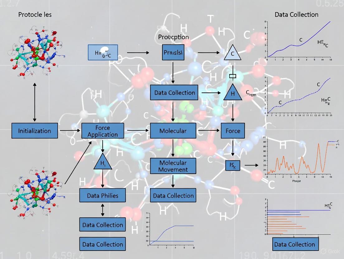
The following diagram illustrates the logical workflow for a typical SMD study, from initial model preparation to final analysis.
Application in Protein Structure Assessment
SMD is a powerful tool for protein quality assessment (QA). A study involving 4,929 computational models from CASP (Critical Assessment of protein Structure Prediction) demonstrated that near-native models (those with high GDT-TS scores) often exhibit higher break forces under SMD-induced stress, indicating greater stability [2]. This allows researchers to select the most accurate structural models by examining their mechanical resistance. The study found that the stability measured by break forces is influenced by bonded interactions, electrostatic interactions, and solvent interactions [2]. However, it is important to note that some near-native models may exhibit lower break forces, suggesting that while high break force is a strong indicator of a correct model, low break force does not automatically rule out model accuracy [2].
Steered Molecular Dynamics (SMD) and rare event sampling algorithms represent powerful computational frameworks for investigating molecular processes that occur on timescales inaccessible to conventional molecular dynamics (MD). These methods provide critical insights into fundamental biological events, such as protein-ligand unbinding, and facilitate the study of rare but physiologically significant conformational transitions. By applying external biases or implementing sophisticated path-sampling techniques, researchers can accelerate these slow processes, enabling the extraction of kinetic parameters, the identification of unbinding pathways, and the exploration of free energy landscapes. This application note details standardized protocols and benchmarking frameworks essential for obtaining rigorous, reproducible results in these advanced simulation domains, with particular emphasis on applications in drug discovery and protein engineering.
Steered Molecular Dynamics for Protein-Ligand Unbinding
Core Principles and Rationale
Protein-ligand unbinding is a critical process in drug discovery, governing residence time and therapeutic efficacy. However, this process occurs over timescales ranging from microseconds to seconds, making it challenging to study with conventional MD [4]. SMD overcomes this limitation by applying an external force to the ligand, systematically pulling it away from the binding pocket to simulate unbinding. This approach generates force-displacement profiles that reveal key interaction barriers and pathways [4]. A critical aspect of SMD setup involves properly restraining protein backbone flexibility to prevent unrealistic system drift while preserving relevant conformational motions during ligand dissociation.
Optimized Restraint Protocol for Protein Flexibility
The choice of restraint strategy significantly influences SMD results. Based on systematic comparisons, restraining all heavy atoms or all Cα atoms overly constrains the system, while restraining too few atoms allows unrealistic protein rotation [4]. An optimized protocol recommends:
- Selection Criteria: Restrain Cα atoms located more than 1.2 nm from the ligand in the initial bound structure [4].
- Force Constant: Apply a harmonic potential with a force constant of 1000 kJ/(mol·nm²) for optimal restraint [4].
- Implementation: This targeted restraint strategy prevents overall protein drift while allowing natural flexibility in the binding site region, leading to more physiologically relevant unbinding pathways.
Table 1: Comparison of Protein Restraint Methods in SMD Simulations
| Restraint Method | Description | Advantages | Limitations |
|---|---|---|---|
| All Heavy Atoms | Restrains all non-hydrogen protein atoms | Prevents overall drift effectively | Overly rigid, may neglect protein motion contributions to unbinding |
| All Cα Atoms | Restrains only alpha-carbon atoms | Reduces excessive rigidity | May still restrict relevant backbone movements |
| Distance-Based Cα Selection | Restrains Cα atoms >1.2 nm from ligand | Balanced approach; prevents drift while maintaining binding site flexibility | Requires careful distance measurement in initial structure |
System Preparation and Simulation Parameters
- Force Fields: Utilize the AMBER ff99SB-ILDN force field for proteins [4].
- Ligand Parameterization: Optimize ligand geometries at the B3LYP/6-31+G(d,p) level and derive atomic charges using the RESP method with the General Amber Force Field (GAFF) [4].
- Solvation: Solvate systems in explicit water with a minimum 0.6 nm distance between the protein surface and box boundaries [4].
- Electrostatics: Apply the Particle Mesh Ewald (PME) method for long-range electrostatic interactions [4].
- Simulation Conditions: Maintain temperature at 300 K using a Langevin thermostat and pressure at 1 atm using a Monte Carlo barostat [4].
Advanced Rare Event Sampling Frameworks
Weighted Ensemble Sampling for Protein Dynamics
For simulating rare events without external steering forces, weighted ensemble (WE) methods provide enhanced conformational sampling. The WESTPA (Weighted Ensemble Simulation Toolkit with Parallelization and Analysis) implementation enables efficient exploration of protein conformational space by running multiple parallel trajectories and periodically resampling them based on progress coordinates [5].
- Progress Coordinates: Utilize Time-lagged Independent Component Analysis (TICA) to define progress coordinates that capture slow conformational modes [5].
- Resampling Strategy: WE simulations run multiple replica trajectories and periodically resample them based on user-defined progress coordinates, enabling better exploration of rare conformational states [5].
- Benchmarking: This approach has been validated across nine diverse proteins ranging from 10-224 residues, spanning various folding complexities and topologies [5].
Enhanced Sampling for Transient Events
Rare, transient events like extreme weather patterns pose particular challenges for sampling algorithms due to their short duration relative to ensemble dispersion times [6]. The TEAMS (Trying-Early Adaptive Multilevel Splitting) algorithm addresses this by:
- Advance Splitting: Perturbing simulations in advance of the target event to allow sufficient ensemble diversification [6].
- Adaptive Multilevel Splitting: Using a progress coordinate to identify promising trajectories for cloning and less promising ones for pruning [6].
- Statistical Reweighting: Applying proper statistical accounting to maintain unbiased probability estimates despite the biased sampling [6].
This approach achieves 5-10 times acceleration in estimating long return periods for extreme events compared to conventional simulation [6].
Standardized Benchmarking and Evaluation
Comprehensive Metrics for Method Validation
Robust benchmarking requires standardized evaluation metrics. A proposed framework includes over 19 different metrics and visualizations across multiple domains [5]:
- Structural Fidelity: Analysis of radius of gyration distributions, contact map differences, and local structural features.
- Slow-Mode Accuracy: Comparison of TICA energy landscapes and identification of slow conformational transitions.
- Statistical Consistency: Calculation of Wasserstein-1 and Kullback-Leibler divergences between simulated and reference distributions.
- Local Geometry: Distributions of bond lengths, angles, and dihedrals compared to reference data.
Benchmark Protein Dataset
A standardized dataset of nine diverse proteins enables consistent method evaluation [5]:
Table 2: Standardized Protein Benchmark Set for Molecular Dynamics Validation
| Protein | Residues | Fold Type | Description | PDB ID |
|---|---|---|---|---|
| Chignolin | 10 | β-hairpin | Tests basic secondary structure formation | 1UAO |
| Trp-cage | 20 | α-helix | Fast-folding with hydrophobic collapse | 1L2Y |
| BBA | 28 | ββα | Mixed secondary structure competition | 1FME |
| Protein B | 53 | 3-helix | Helix packing dynamics | 1PRB |
| Homeodomain | 54 | 3-helix bundle | DNA-binding domain with stable fold | 1ENH |
| Protein G | 56 | α/β | Complex topology formation | 1PGA |
| WW Domain | 37 | β-sheet | Challenging β-sheet topology | 1E0L |
| a3D | 73 | 3-helix | Synthetic helical bundle, tests designability | 2A3D |
| λ-repressor | 224 | 5-helix | Tests scalability for large proteins | 1LMB |
Visualization and Workflow Diagrams
SMD Unbinding Protocol Workflow
Weighted Ensemble Sampling Workflow
Research Reagent Solutions
Table 3: Essential Research Reagents and Computational Tools
| Tool/Reagent | Type | Function | Application Notes |
|---|---|---|---|
| WESTPA 2.0 | Software | Weighted ensemble sampling implementation | Open-source; enables efficient rare event sampling [5] |
| OpenMM | Software | High-performance MD simulation | Supports both CPU and GPU acceleration [5] |
| AMBER ff99SB-ILDN | Force Field | Protein force field parameters | Provides accurate protein dynamics [4] |
| GAFF | Force Field | General Amber Force Field for small molecules | Used for ligand parameterization [4] |
| GROMACS | Software | Molecular dynamics package | Version 2020+; used for system preparation [4] |
| PyMOL | Software | Molecular visualization | Repairs missing residues in PDB structures [4] |
| Gaussian 16 | Software | Quantum chemistry package | Optimizes ligand geometry and calculates electrostatic potentials [4] |
The integration of Steered Molecular Dynamics and rare event sampling algorithms provides a powerful framework for investigating molecular processes critical to drug discovery and protein engineering. The protocols detailed herein—particularly the optimized restraint strategies for SMD and standardized benchmarking approaches for enhanced sampling—enable rigorous investigation of protein-ligand unbinding and conformational transitions. By adopting these standardized methods and utilizing the comprehensive benchmarking tools, researchers can achieve more reproducible and biologically relevant insights into molecular mechanisms, ultimately accelerating therapeutic development and our understanding of biomolecular function.
Steered Molecular Dynamics (SMD) is a powerful computational technique that applies external forces to biomolecular systems to simulate processes like ligand unbinding and protein unfolding. The reliability and quantitative accuracy of SMD simulations are critically dependent on the careful selection of three fundamental parameters: pulling force, pulling velocity, and the reaction coordinate. These parameters govern the non-equilibrium work applied to the system and determine how closely the simulation mimics real-world biological processes. Proper configuration of these elements is essential for obtaining meaningful kinetic and thermodynamic data, which is increasingly valuable in drug discovery for predicting properties such as ligand residence times and binding affinities [7] [8] [9].
Within drug development, SMD has emerged as a crucial tool for evaluating ligand-receptor interactions, providing atomic-level insights that complement experimental data. The temporal stability of ligand-receptor complexes, characterized by the residence time (RT), is now recognized as a critical factor influencing drug efficacy and pharmacodynamics. As conventional affinity-based parameters often fall short in predicting in vivo effectiveness, SMD offers a pathway to estimate the dissociation rate constant (k~off~), the inverse of which defines the RT [9]. This application underscores the importance of precise parameter selection in SMD simulations to generate biologically relevant data for kinetic-based drug development.
Theoretical Foundation of SMD
The Jarzynski Equality and Non-Equilibrium Dynamics
SMD operates under non-equilibrium conditions, where continuously changing the distance between molecular groups applies work to the system. The Jarzynski equality provides the theoretical foundation for extracting equilibrium free-energy differences from these non-equilibrium simulations. It states that the equilibrium free-energy difference, ΔG~AB~, between two states A and B can be obtained from an exponential average of the work, W~AB~, performed over many non-equilibrium paths:
ΔG~AB~ = -k~B~T log⟨e^(-βW~AB~)⟩~A~
where k~B~ is Boltzmann's constant, T is the absolute temperature, β = 1/k~B~T, and the angular brackets denote averaging over a canonical ensemble of the initial state A [10]. This relationship enables researchers to derive meaningful thermodynamic information from the forced processes simulated in SMD, bridging the gap between non-equilibrium manipulations and equilibrium properties.
The Bell-Evans Model for Kinetic Insights
For investigating dissociation kinetics, the Bell-Evans model offers a framework to connect SMD results with experimental observables. This model relates the unbinding force (F~R~) measured in simulations to the dissociation rate constant (k~off~) at equilibrium:
F~R~ = (k~B~T / x~b~) ln[(F'x~b~) / (k~B~T k~off~)]
In this equation, x~b~ represents the reaction coordinate projection between the bound and transition state, and F' is the loading rate (the product of the force constant and pulling velocity) [8]. This theoretical foundation allows researchers to predict absolute residence times of drug candidates, such as ligands targeting G-protein-coupled receptors (GPCRs), by analyzing forced unbinding events [8].
Critical SMD Parameters and Their Optimization
Pulling Velocity
Pulling velocity is perhaps the most critical parameter in SMD simulations, as it directly influences the magnitude of force required for dissociation and the biological relevance of the results. While faster pulling speeds enable computationally efficient sampling, they introduce non-equilibrium effects that can distort the energy landscape and mechanism. The selection of appropriate pulling velocities depends on the specific system and research question, with slower velocities generally providing more physiologically relevant data.
Table 1: Typical Pulling Velocity Ranges in SMD Studies
| System Type | Pulling Velocity Range | Application Context | Key Considerations |
|---|---|---|---|
| Ligand-Protein Unbinding [8] | 0.0001 - 0.0010 nm/ps | GPCR-ligand dissociation | Slower velocities (e.g., 0.0001 nm/ps) approximate closer to equilibrium conditions |
| Membrane Extraction [11] | 0.5 nm/ns (5 Å/ns) | Small molecule and peptide affinity | Constant velocity pulling with sufficiently large force constant |
| Protein Unfolding [12] | Varies by method | Talin rod subdomain unfolding | High speeds generate artificial structural states; balance with computational cost |
Pulling Force and Spring Constant
The pulling force in SMD simulations is typically applied through a harmonic potential, with the spring constant (elastic constant) determining the stiffness of this connection. This parameter controls the sensitivity of the method and influences the pathway of the forced reaction. A balance must be struck—too soft a spring may not adequately transfer the pulling force, while too stiff a spring may suppress thermal fluctuations essential for exploring natural pathways.
Table 2: Spring Constants and Force Application Methods
| Parameter | Typical Values | Impact on Simulation | Representative Use Cases |
|---|---|---|---|
| Spring Constant [8] [11] | 600 kJ/mol/nm² / 2.4 kcal/mol/Ų | Softer springs allow more system flexibility; stiffer springs provide tighter control | GPCR-ligand unbinding; small molecule membrane extraction |
| Constant Force Pulling [10] | Applied directly | Linear potential, no reference distance | Less common for free energy calculations |
| Umbrella Pulling [10] | Harmonic potential | Force proportional to displacement | Common in SMD for its numerical stability |
The selection of spring constant significantly affects the simulation outcome. Studies on membrane-interacting molecules revealed that spring stiffness is "crucially important to reveal specific events that occur during the molecule behavior," directly influencing methodological sensitivity [11]. Similarly, the choice of pulling group "highly influenced the reaction pathway," making force profiles unique "fingerprints" of these induced pathways [11].
Reaction Coordinates and Pulling Geometries
Reaction coordinates define the collective variables along which the system is steered, serving as computational observables that map the progression of the molecular process. GROMACS refers to this as the "pull code," which applies forces or constraints on these collective variables [10]. The appropriate selection of reaction coordinates is essential for efficiently sampling the relevant conformational changes and obtaining meaningful results.
Table 3: Common Reaction Coordinate Geometries in SMD
| Geometry Type | Definition | Application Context | Key Features |
|---|---|---|---|
| Distance [10] | Distance between two groups' centers of mass | Ligand unbinding, molecular dissociation | Most common; follows natural separation vector |
| Direction [10] | Pulling along a defined vector | Membrane protein pulling against fixed orientation | Avoid with freely oriented reference groups |
| Direction-relative [10] | Pulling along a vector defined by two additional groups | Systems without fixed orientation | Prevents unwanted torque forces |
| Cylinder [10] | 1D distance with cylindrical reference | Layered systems (e.g., lipid bilayers) | Dynamically uses reference atoms within cylinder radius |
| Angle/Dihedral [10] | Angle between vectors defined by multiple groups | Conformational changes, rotational motions | Requires 4 groups for angle, 6 for dihedral |
For complex systems like lipid bilayers, specialized geometries such as the cylinder geometry can provide more locally relevant reaction coordinates. This approach dynamically selects only those reference atoms within a defined cylinder around the pull vector, with distance-based weighting to minimize radial force effects [10]. For periodic systems where plain center-of-mass definitions become problematic, such as water slabs connected through periodic boundaries, cosine-shaped weighting profiles can provide unique and continuous reference positions [10].
Experimental Protocols for SMD Simulations
Protocol 1: Ligand-Protein Unbinding Kinetics
This protocol outlines the procedure for estimating ligand residence times through forced unbinding simulations, adapted from studies on GPCR-ligand systems [8].
Step 1: System Preparation and Equilibration
- Obtain the initial ligand-protein complex structure from experimental data or molecular docking.
- Solvate the system in an appropriate water model (e.g., TIP3P) and add ions to physiological concentration (e.g., 0.15 M KCl).
- Energy minimization using steepest descent or conjugate gradient algorithm until convergence.
- Equilibration with position restraints on protein heavy atoms (typically 100-1000 kJ/mol/nm²):
- NVT ensemble equilibration for 100-500 ps
- NPT ensemble equilibration for 1-5 ns
- Unrestrained production MD simulation for 50-100 ns to ensure system stability.
Step 2: SMD Simulation Setup
- Select starting structure from the equilibrated trajectory based on root mean-square deviation (RMSD) stability.
- Define the reaction coordinate as the distance between the ligand's center of mass and the binding pocket center.
- Configure pulling parameters:
- Pulling velocity: 0.0001-0.0010 nm/ps
- Spring constant: 600 kJ/mol/nm²
- Pulling geometry: distance (along the vector between groups)
Step 3: Running SMD Simulations
- Perform multiple SMD runs (minimum 3-5 replicates) with different initial velocities.
- For each simulation, record:
- Time-dependent pulling force
- Reaction coordinate value (separation distance)
- Work performed on the system
- Key interactions (hydrogen bonds, hydrophobic contacts)
Step 4: Data Analysis and Residence Time Calculation
- Extract maximum unbinding force (F~max~) and total work from each trajectory.
- Apply the Bell-Evans model to estimate k~off~ values.
- Calculate residence time as RT = 1/k~off~.
- Compare with experimental data if available for validation.
Protocol 2: Small Molecule Membrane Permeability Assessment
This protocol describes the use of SMD for studying the membrane affinity and permeation of small molecules, based on methodologies for analyzing membrane-interacting molecules [13] [11].
Step 1: Membrane System Preparation
- Construct a lipid bilayer representative of the biological membrane of interest (e.g., POPC for mammalian cells).
- Hydrate the bilayer with appropriate water model.
- Insert the small molecule of interest at the membrane-water interface.
- Minimize and equilibrate the full system:
- Energy minimization with restraints on lipid and solute atoms.
- Gradual relaxation of restraints over multiple equilibration steps.
- Unrestrained equilibration for 20-100 ns until membrane properties stabilize.
Step 2: SMD Parameter Optimization
- Test different spring constants (e.g., 2.4-10 kcal/mol/Ų) to balance sensitivity and pathway exploration.
- Select pulling velocity based on system size and computational resources (e.g., 0.5-5 Å/ns).
- Choose appropriate pulling groups that represent the molecular orientation during permeation.
- Define reaction coordinate as the distance between molecule center of mass and membrane center along the bilayer normal.
Step 3: Extraction Simulations
- Perform multiple SMD runs pulling the molecule from the membrane interior to the water phase.
- Vary the initial position and orientation within the membrane.
- Record force profiles, work values, and molecular orientation during extraction.
- Identify key interactions with lipid headgroups and hydrocarbon chains.
Step 4: Potential of Mean Force (PMF) Calculation
- Use the Jarzynski equality to estimate PMF from multiple nonequilibrium work values.
- Alternatively, combine with umbrella sampling for more accurate free energy profiles.
- Analyze the energy barriers associated with membrane crossing.
- Correlate with experimental permeability data when available.
Visualization and Workflow Diagrams
SMD Simulation Workflow: This diagram outlines the comprehensive workflow for conducting steered molecular dynamics simulations, from initial system preparation to final results interpretation.
SMD Parameter Optimization Logic: This diagram illustrates the decision process and evaluation criteria for optimizing critical SMD parameters to ensure reliable and biologically relevant results.
The Scientist's Toolkit: Essential Research Reagents and Computational Solutions
Table 4: Key Research Reagents and Computational Tools for SMD
| Tool/Category | Specific Examples | Function/Role in SMD |
|---|---|---|
| MD Simulation Software [10] [12] | GROMACS, NAMD, AMBER, CHARMM | Primary engines for running SMD simulations with implemented pulling algorithms |
| Force Fields [14] | CHARMM27, CHARMM36, AMBER, GROMOS | Provide empirical potential energy functions for different molecular types |
| Analysis Tools | GROMACS analysis suite, VMD, MDAnalysis | Process trajectories, calculate forces, work, and monitor interactions |
| Enhanced Sampling Methods [12] | Umbrella Sampling, Boxed MD (BXD) | Complement SMD for free energy calculations and improved sampling |
| Visualization Software | VMD, PyMOL, Chimera | System setup, trajectory analysis, and result presentation |
| Specialized Pulling Geometries [10] | Distance, direction, cylinder, angle/dihedral | Define reaction coordinates matched to specific biological questions |
The rigorous application of SMD in studying specific atomic motions demands careful attention to three essential parameters: pulling velocity, which must balance computational efficiency with biological realism; pulling force and spring constant, which control the sensitivity and pathway of the forced process; and reaction coordinates, which must accurately capture the relevant molecular motions. The protocols and guidelines presented here provide a framework for researchers to implement SMD techniques effectively across various applications, from drug discovery to membrane permeability studies. As MD methodologies continue to advance, the precision in parameter selection will further enhance the value of SMD in bridging molecular simulations with experimental observables, particularly in the critical assessment of binding kinetics and drug-target interactions.
Steered Molecular Dynamics (SMD) is a powerful computational technique that applies external forces to a molecular system to induce specific motions or processes, such as ligand unbinding or conformational changes, on computationally accessible timescales [15]. This method is particularly valuable for studying biological events that occur too slowly for standard MD simulations to capture efficiently. Within the broader thesis on SMD protocols for studying specific atomic motions, this document provides detailed application notes and protocols for configuring and executing SMD simulations within realistic membrane and solvent environments, which are critical for studying biologically relevant systems like membrane-embedded receptors.
Key Concepts and Energetics
Understanding the forces and energies governing molecular systems is fundamental to designing effective SMD simulations. The table below summarizes key quantitative findings from recent multiscale simulation studies.
Table 1: Key Quantitative Data from Multiscale Simulation Studies
| System / Parameter Studied | Computational Method | Key Quantitative Finding | Significance |
|---|---|---|---|
| CO₂ Capture in Aqueous MEA [16] | Steered Rare-Event (COLVARS) | Effective 1D diffusivity: 8.46 × 10⁻¹¹ m²/s | Two orders lower than bulk diffusivity, reveals kinetic bottleneck before chemical binding. |
| CO₂ Binding to MEA Amine Group [16] | DFT-D3 | Binding Energy: -0.37 eV | Confirms stronger binding to amine vs. hydroxyl group (-0.25 eV), guiding solvent design. |
| CO₂-MEA Reaction Barrier [16] | CI-NEB | Forward Barrier: 0.11 eV; Reverse Barrier: 0.39 eV | Supports kinetic feasibility of the CO₂ capture reaction. |
| GPCR Intracellular Opening [17] | Classical MD (556.5 µs dataset) | Transition time (apo): Closed→Intermediate ~0.5 µs; Closed→Open ~7.8 µs | Reveals spontaneous "breathing" motions and the impact of ligand binding on receptor dynamics. |
| SPEEK Membrane Proton Conductivity [18] | Classical MD (Parameter Analysis) | DREIDING FF Tg: 461 K; COMPASS III conductivity: 16.6 mS/cm | Highlights critical impact of force field selection on matching different experimental properties. |
The Scientist's Toolkit: Essential Reagents and Materials
The following table details key components required to set up and run SMD simulations of biological systems in realistic environments.
Table 2: Research Reagent Solutions for Realistic Membrane and Solvent Simulations
| Item Name | Function / Description | Example / Consideration |
|---|---|---|
| Molecular System Builder | Software to assemble the initial atomic coordinates of the protein, membrane, and solvent. | CHARMM-GUI, PACKMOL-Memgen, VMD's Membrane Plugin. |
| Force Field | A set of empirical parameters defining potential energy functions for the interactions between atoms. | CHARMM36, AMBER, OPLS-AA; Selection is critical for accuracy [18]. |
| Membrane Lipid Types | Pre-equilibrated lipid bilayers of defined composition to create a realistic membrane environment. | POPC, POPE, or complex mixtures mimicking native membranes (e.g., for GPCR studies [17]). |
| Explicit Solvent Model | Water molecules and ions placed around the solute to mimic a physiological aqueous environment. | TIP3P, SPC/E water models; ion concentration (e.g., 0.15 M NaCl) to neutralize charge. |
| Steering & Analysis Tool | Software package that implements SMD algorithms and tools for analyzing the resulting trajectories. | NAMD (with Tcl scripting), GROMACS (with pull code), COLVARS module [16]. |
| Enhanced Sampling Module | Advanced sampling modules for rare-event sampling alongside or in place of direct steering. | PLUMED, COLVARS (for metadynamics, umbrella sampling) [16]. |
Experimental Protocols
Protocol: SMD Simulation of a Ligand Exiting a GPCR via a Lateral Membrane Pathway
This protocol outlines the steps to investigate ligand egress pathways from a membrane-embedded GPCR using SMD, based on insights from large-scale MD datasets [17].
I. System Preparation
- Initial Structure: Obtain a high-resolution structure of the GPCR-ligand complex from the PDB or GPCRmd [17]. For apo systems, remove the ligand.
- Membrane and Solvent Embedding: a. Use a system builder (e.g., CHARMM-GUI) to embed the receptor in an asymmetric lipid bilayer representative of native membranes. b. Solvate the entire system in a rectangular water box using a model like TIP3P. c. Add ions to neutralize the system's net charge and then add more salt to achieve a physiological concentration (e.g., 0.15 M NaCl).
- Energy Minimization and Equilibration: a. Perform steepest descent energy minimization to remove bad atomic contacts. b. Equilibrate the system in stages, first restraining the protein and ligand heavy atoms, then gradually releasing the restraints over several hundred nanoseconds under NPT ensemble conditions. Use the Berendsen barostat for pressure coupling, which has been shown to provide stable control [18].
II. Steered Molecular Dynamics Setup
- Collective Variable (CV) Definition: Define a CV that describes the ligand's dissociation path. For lateral egress, this could be the distance between the ligand's center of mass and the center of the membrane bilayer, combined with its radial coordinate within the membrane plane.
- SMD Parameters: a. Steering Method: Use constant velocity pulling. b. Selection of Atoms: Attach the virtual spring to the heavy atoms of the ligand. Restrain the Cα atoms of the transmembrane helices of the GPCR to prevent unrealistic rigid-body motion of the protein. c. Pulling Speed: Apply a slow, constant velocity (e.g., 0.5-1.0 Å/ns) to the CV to approximate quasi-adiabatic pulling. Multiple trials with different speeds can be used to check for speed-dependence. d. Force Constant: Use a sufficiently high spring constant (e.g., 100-500 kcal/mol/Ų) to keep the ligand close to the intended path.
III. Production Run and Analysis
- Execute SMD: Run multiple, independent SMD simulations (≥10) to account for stochasticity and identify consistent pathways.
- Monitor Key Metrics: Record the time series of the applied force, the CV, and the work performed on the system.
- Pathway Analysis: Cluster the successful egress trajectories to identify common pathways and intermediates. Analyze the protein-lipid interactions around the egress site, as lipid insertions can mark allosteric sites and lateral gateways [17].
- Potential of Mean Force (PMF): Use the Jarzynski equality [15] or umbrella sampling on the identified pathway to calculate the free energy profile (PMF) associated with ligand egress.
Protocol: Multiscale Modeling of Solvent-Solute Interactions
This protocol describes a three-tier approach, combining DFT, classical MD, and steered rare-event sampling to study specific interactions, such as CO₂ capture by amine-based solvents [16].
I. Electronic Structure Calculations (DFT)
- Objective: Characterize the strength and mechanism of the core chemical interaction.
- Procedure: a. Model the solute (e.g., CO₂) and the binding site (e.g., MEA molecule) in a gas-phase or implicit solvent QM calculation. b. Perform geometry optimization to find the stable bound state and the transition state for the reaction using methods like CI-NEB [16]. c. Calculate the binding energy and electronic properties like charge transfer. Apply external fields if relevant to study their effect on the interaction [16].
II. Classical Molecular Dynamics (MD)
- Objective: Understand the structure, dynamics, and transport at the gas-liquid or solution interface.
- Procedure: a. Build a system with explicit solvent molecules (e.g., 26 wt% MEA in water [16]). b. Run classical MD simulations in the NPT ensemble to equilibrate density and study bulk properties. c. Analyze radial distribution functions (RDFs) to determine preferential association (e.g., CO₂ with amine groups). Calculate bulk diffusion coefficients from mean squared displacement (MSD).
III. Steered Rare-Event Sampling (COLVARS)
- Objective: Resolve the kinetically hindered association step at the interface.
- Procedure: a. Define a collective variable that captures the approach of the solute to the binding site. b. Use the COLVARS module to perform biased sampling along this CV, such as umbrella sampling or metadynamics. c. Extract the effective diffusivity along the reaction coordinate and reconstruct the free energy profile [16].
Workflow Visualization
The following diagram illustrates the logical workflow for integrating multiscale modeling and SMD protocols.
Implementing SMD Protocols: Setup, Execution, and Analysis for Drug Discovery
The accuracy of steered molecular dynamics (sMD) simulations is fundamentally dependent on the initial construction and solvation of the protein-ligand system. Proper system preparation ensures that the simulated atomic motions and forces reflect near-physiological conditions, providing reliable insights into molecular mechanisms. This protocol details the comprehensive process of building biologically relevant protein-ligand complexes and applying appropriate solvation models, specifically tailored for sMD studies of specific atomic motions. We provide quantitative comparisons of solvation methods and step-by-step methodologies to ensure reproducibility in computational drug discovery research.
Solvation Models: A Quantitative Comparison
Solvation models approximate the effect of solvent on biomolecular structure and dynamics, with significant implications for simulation accuracy and computational cost. The choice between implicit and explicit solvation involves balancing physical realism with computational efficiency.
Table 1: Comparison of Implicit Solvation Models for MD Simulations
| Model Type | Theoretical Basis | Computational Speed | Key Advantages | Key Limitations |
|---|---|---|---|---|
| SASA [19] [20] | Solvation free energy proportional to solvent-accessible surface area | Very Fast | Simple calculation; direct free energy estimation; suitable for quick screening | Neglects specific electrostatic effects and hydrogen bonding |
| Generalized Born (GB) [19] [20] | Approximates Poisson-Boltzmann electrostatics using pairwise interactions | Fast | Good balance of speed and accuracy for electrostatic interactions; widely used | Accuracy can vary for non-standard molecular shapes; parameter-dependent |
| Poisson-Boltzmann (PB) [19] [20] | Numerical solution of the continuum electrostatics equation | Slow | High accuracy for electrostatic interactions; considered a gold standard for implicit electrostatics | Computationally expensive; requires numerical grid calculation |
| EEF1 [19] | Gaussian exclusion model with volume integration | Fast | 50% faster than vacuum simulations; used in CHARMM19 force field | Simplifies electrostatics; ionic side chains are neutralized |
Implicit solvation represents the solvent as a continuous medium rather than individual molecules, significantly accelerating simulations by reducing the number of particles and smoothing the energy landscape [19] [20]. The Generalized Born (GB) model augmented with a hydrophobic solvent-accessible surface area (SASA) term, often termed GBSA, is among the most commonly used implicit solvent combinations in molecular mechanics (MM/GBSA) [20]. While valuable for conformational sampling, implicit models have limitations: they lack explicit hydrogen bonding with solvent molecules, neglect viscosity that affects solute motion, and require additional terms to account for the hydrophobic effect [20].
Explicit solvation, in contrast, places individual water molecules around the solute, providing a more physically realistic representation of specific solute-solvent interactions, such as hydrogen bond fluctuations and water bridging effects [19]. However, this comes at a high computational cost, requiring significant resources for simulating the large number of water molecules and achieving proper equilibrium [19] [21]. For sMD simulations, where enhanced sampling of specific pathways is often the goal, a trade-off between realism and efficiency must be carefully considered.
Experimental Protocols
Protocol 1: Protein-Ligand Complex Construction via Molecular Docking
Objective: To generate a structurally accurate and physically plausible protein-ligand complex for subsequent solvation and sMD simulation.
Materials and Software:
- Protein Data Bank (PDB) file of the target protein.
- 2D or 3D chemical structure file of the ligand (e.g., MOL2, SDF).
- Molecular docking software (e.g., AutoDock Vina, Glide, SurfDock).
- Visualization software (e.g., PyMOL).
Methodology:
- Protein Preparation:
- Obtain the protein structure from the PDB. Remove crystallographic water molecules and heteroatoms unless they are known to be functionally critical.
- Add missing hydrogen atoms appropriate for the physiological pH (e.g., 7.4).
- Assign partial atomic charges using force field parameters (e.g., AMBER, CHARMM). Ensure histidine protonation states are correct.
Ligand Preparation:
- Generate a 3D conformation of the ligand from its 2D structure.
- Minimize the ligand geometry using molecular mechanics to relieve steric clashes.
- Assign accurate partial charges and determine rotatable bonds. Gasteiger charges are commonly used for docking.
Binding Site Definition:
- If the binding site is known from experimental data, define the search space using a grid box centered on the site. A typical box size is 20-25 Å per side.
- For blind docking, encompass the entire protein surface within the grid.
Molecular Docking:
- Run the docking simulation to generate multiple ligand poses (e.g., 10-20).
- Select the top-ranked pose based on the docking scoring function. However, be cautious, as a favorable score does not guarantee biological relevance [22].
Pose Validation and Selection:
- Critically assess the physical plausibility of the selected pose. Use tools like PoseBusters to check for geometric distortions, steric clashes, and correct stereochemistry [22].
- Prioritize poses that recapitulate known key interactions from crystallographic data, such as hydrogen bonds with charged residues (aspartate, arginine, histidine) which are highly frequent in binding pockets [23].
- Visually inspect the pose in PyMOL to ensure the ligand orientation is reasonable.
Visualization Workflow for Complex Analysis:
Protocol 2: Solvation of the Protein-Ligand Complex
Objective: To embed the docked protein-ligand complex in a solvated environment, preparing it for stable MD and sMD simulations.
Materials and Software:
- Prepared protein-ligand complex from Protocol 1.
- Solvation software (e.g.,
gmx solvatefrom GROMACS,LEaPfrom AMBER,tleap). - Force field parameter files for water (e.g., TIP3P, SPC).
Methodology: A. Explicit Solvation Setup:
- Place Complex in a Simulation Box:
- Center the protein-ligand complex in a predefined box (e.g., cubic, dodecahedral). The box should extend at least 10 Å from the solute surface to avoid periodic image artifacts.
- Add Solvent Molecules:
- Fill the box with explicit water molecules. The TIP3P model is a common choice for simulating biomolecules.
- For physiological conditions, replace random water molecules with ions (e.g., Na+, Cl-) to neutralize the system's net charge and achieve a desired salt concentration (e.g., 150 mM NaCl).
B. Implicit Solvation Setup (for specific applications):
- Model Selection:
- Choose an appropriate implicit solvent model based on the research question (see Table 1). For a balance of speed and accuracy, GBSA is often recommended.
- Parameterization:
- In the MD simulation input parameters, specify the implicit solvent model (e.g.,
GBSAin AMBER) instead of defining an explicit water box. No further system building is required, as the solvent is modeled mathematically.
- In the MD simulation input parameters, specify the implicit solvent model (e.g.,
Diagram: Solvation Model Selection Logic:
Protocol 3: System Validation via Energy Minimization and Equilibration
Objective: To ensure the solvated system is stable and has no steric conflicts before initiating production sMD runs.
Methodology:
- Energy Minimization:
- Perform steepest descent or conjugate gradient minimization to remove any bad van der Waals contacts introduced during solvation.
- Run until the maximum force falls below a specified tolerance (e.g., 1000 kJ/mol/nm).
- Equilibration:
- Conduct a short (100-200 ps) MD simulation in the NVT (constant Number, Volume, Temperature) ensemble to stabilize the system temperature (e.g., 310 K).
- Follow with a short (100-200 ps) NPT (constant Number, Pressure, Temperature) ensemble simulation to stabilize the system density and pressure (e.g., 1 bar).
- Monitor the root mean square deviation (RMSD) of the protein backbone and ligand. A stable RMSD (typically 1-2 Å) indicates the system has equilibrated [23].
Results and Data Presentation
Proper system preparation leads to stable simulations that can provide meaningful data for sMD studies. Key metrics to monitor during and after preparation include structural stability and interaction consistency.
Table 2: Expected Ranges for Key Validation Metrics Post-Equilibration [24] [23]
| Metric | Description | Stable Range | Interpretation |
|---|---|---|---|
| Protein Backbone RMSD | Measures overall protein stability relative to the starting structure. | 1.5 - 2.5 Å | Values ≤ 2-3 Å indicate a stable protein fold. |
| Ligand RMSD | Measures ligand stability within the binding pocket. | 1.0 - 2.0 Å | Values ≤ 2 Å suggest the ligand is stably bound. |
| Binding Residue RMSD | Measures stability of residues directly interacting with the ligand. | 0.7 - 1.5 Å (IQR*) | Low fluctuation is crucial for reliable sMD starting points. |
| SASA (Min/Max) | Toggles the solvent exposure of binding residues. | ~2.7 / ~3.2 Ų (median) | Indicates a consistent binding interface with limited solvent penetration. |
| H-bond Occupancy | Percentage of simulation time a specific H-bond is maintained. | >70% (High Occupancy) | Sustained H-bonds are critical for stable binding and realistic sMD steering. |
IQR: Interquartile Range [23].
Analysis of 100 target-ligand complexes revealed that 86.5% of key binding residues form hydrogen bonds with high occupancy (maintained for 71-100% of the simulation time) [23]. This underscores the importance of validating that prepared systems can replicate such persistent, biologically relevant interactions. Furthermore, binding pockets are frequently enriched with charged residues (56%), particularly aspartate, histidine, and arginine, which should be correctly modeled and protonated during protein preparation [23].
The Scientist's Toolkit: Research Reagent Solutions
Table 3: Essential Software and Force Fields for System Preparation
| Item Name | Function / Application | Reference / Source |
|---|---|---|
| AutoDock Vina | Molecular docking software for predicting protein-ligand binding poses and affinity. | [22] |
| Glide (Schrödinger) | High-performance molecular docking tool with rigorous scoring functions for pose prediction. | [22] |
| GROMACS | Versatile MD simulation package used for system solvation, energy minimization, equilibration, and production runs. | [24] [21] |
| AMBER Tools | Suite of programs for MD simulations, including the tleap module for system building and solvation. |
[19] |
| PyMOL | Molecular visualization system for analyzing protein-ligand complexes, checking poses, and creating publication-quality images. | [25] [26] |
| CHARMM Force Field | A set of parameters for molecular mechanics, dynamics, and solvation energy calculations of biomolecules. | [19] [20] |
| AMBER Force Field | Another widely used set of parameters for simulating biomolecules, often used with the Generalized Born solvation model. | [19] [20] |
| PoseBusters | A validation toolkit to check the physical plausibility and chemical correctness of AI-generated molecular docking poses. | [22] |
Defining Pulling Groups and Reaction Coordinates for Specific Atomic Motions
Steered molecular dynamics (SMD) simulations enable researchers to investigate specific atomic motions by applying external forces to biomolecular systems. This application note details established protocols for defining pulling groups and reaction coordinates, which are critical for studying processes like ligand unbinding and protein domain rearrangement. We summarize quantitative parameters from foundational studies and provide a detailed methodology for implementing SMD in GROMACS, facilitating its application in drug development research.
In Steered Molecular Dynamics (SMD), a reaction coordinate is an abstract one-dimensional coordinate that represents the progress of a molecular process along a chosen pathway [27]. It parameterizes the reaction at the level of the molecular entities involved, often corresponding to a geometric parameter like a distance or angle that changes during the conversion [27]. The careful definition of this coordinate and the groups to which force is applied is paramount for obtaining meaningful thermodynamic and kinetic information.
The core hypothesis underpinning SMD applications is that a biomolecular structure's resistance to an externally applied force correlates with its stability and structural accuracy [2]. This principle allows SMD to be used for assessing protein model quality, exploring unfolding pathways, and studying mechanical resistance in molecular interactions.
Theoretical Framework
The Reaction Coordinate in Chemical Physics
A reaction coordinate is formally a function that maps any point in the system's high-dimensional phase space to a single real number [28]. For complex processes in condensed phase and biomolecular systems, the natural reaction coordinate can be defined as a maximally predictive one-dimensional projection of the system's dynamics [28]. This means that, of all possible one-dimensional measurements, the natural reaction coordinate is the most informative about the system's future evolution, effectively capturing the dynamics of the rate-limiting bottlenecks.
For SMD and other enhanced sampling methods, collective variables (CVs) are employed. A collective variable is a function of a set of atomic coordinates, ( CV = A\{x_i\} ), which reduces the many atomic degrees of freedom to a lower-dimensional set that still describes the crucial characteristics of the system [27]. The reaction coordinate itself is then a continuous function of these collective variables [27].
Common Reaction Coordinate Geometries
The choice of geometry for the reaction coordinate depends on the biological process being simulated. The table below summarizes the most common types.
Table 1: Common Reaction Coordinate Geometries in SMD
| Geometry Type | Mathematical Description | Typical Application |
|---|---|---|
| Distance | Pulling along the vector connecting two groups [29]. | Ligand unbinding from a protein active site [29]. |
| Directional Distance | Distance projection along a specific vector (e.g., pull_coord1_dim = N N Y for Z-axis only) [29]. |
Guiding a molecule through a protein channel or pore. |
| Bond Rotation | Dihedral angle between groups on two atoms [30]. | Conformational analysis of side chains or linkers. |
| Radius of Gyration | Overall compactness of a molecule [31]. | Protein folding/unfolding studies. |
| Center of Mass Distance | Distance between the centers of mass of two groups [31]. | Domain separation in multi-domain proteins. |
Experimental Protocols
Defining Pulling Groups and Parameters in GROMACS
The following protocol details the setup for a ligand unbinding simulation using GROMACS, a widely used MD software package.
1. System Preparation:
- Prepare your protein-ligand complex structure file (e.g.,
.pdbor.gro). - Generate a topology for the entire system, ensuring the ligand parameters are correctly defined.
- Solvate the system in a suitable water model (e.g., TIP3P) and add ions to neutralize the charge.
2. Define Pulling Groups:
In your .mdp (molecular dynamics parameters) file, specify the groups to be pulled. It is generally recommended to use a large, stationary group (like the protein) as the reference and pull the smaller group (like the ligand) relative to it [29].
3. Configure the Reaction Coordinate: This example uses a directional distance geometry to pull the ligand away from the protein along the Z-axis.
4. Execution and Output:
- Run the SMD simulation using
gmx mdrun. - Key output files include
pullf.xvg(containing the applied force over time) andpullx.xvg(containing the position of the pulled group over time).
Workflow Diagram
The following diagram illustrates the logical workflow for setting up and running an SMD simulation.
SMD Setup and Execution Workflow
The Scientist's Toolkit
This section lists key reagents and computational tools essential for conducting SMD simulations.
Table 2: Essential Research Reagents and Tools for SMD
| Item / Resource | Function / Purpose | Example / Note |
|---|---|---|
| MD Simulation Engine | Software to perform the numerical integration of the equations of motion. | GROMACS [29], AMBER [32], NAMD. |
| Biomolecular Force Field | A set of empirical potentials that describe the interatomic interactions. | CHARMM, AMBER ff99SB/parmbsc0 [32], Martini (coarse-grained) [31]. |
| Visualization Software | For visualizing the trajectory, monitoring the pull, and debugging. | VMD, PyMol, ChimeraX. |
| Analysis Tools | Built-in or community scripts for processing SMD output. | GROMACS gmx analyze, gmx wham for Umbrella Sampling. |
| Elastic Network Model | Applied to folded domains to maintain their rigidity while allowing flexible linkers to move freely [31]. | Harmonic potential on backbone beads (force constant ~500 kJ mol⁻¹ nm⁻²) [31]. |
Troubleshooting and Best Practices
Successful application of SMD requires careful parameter selection and systematic troubleshooting.
Table 3: Troubleshooting Common SMD Issues
| Problem | Potential Cause | Solution |
|---|---|---|
| Ligand does not move | Force constant too low; steric clashes; incorrect group definition. | Increase pull_coord1_k (e.g., to 1500); check group indices in .mdp [29]. |
| Simulation crashes with "Pull reference distance... needs to be non-negative" | The reference distance for the pulling coordinate has become negative [29]. | Ensure the larger group is set as the reference; check pulling direction; increase force constant [29]. |
| Ligand moves but not along desired path | Incorrect geometry or pulling dimension. | Use pull_coord1_dim to restrict pulling to a specific axis (e.g., N N Y for Z-axis) [29]. |
| Pulling induces unrealistic distortion | Pulling speed is too high. | Reduce pull_coord1_rate (e.g., to 0.001 nm/ps) to approach quasi-equilibrium pulling. |
| Ligand cannot pass through a channel | The protein structure might be in a closed state [29]. | Consider using an experimentally determined open-state structure if available [29]. |
A critical best practice is to invert the pulling direction by changing the sign of the pull_coord1_rate parameter [29]. For instance, if a positive rate pulls a ligand "down," a negative rate will pull it "up," though the success of this depends on the steric accessibility of the new path [29].
Practical Workflow in GROMACS and Other MD Software Packages
Molecular dynamics (MD) simulation is a cornerstone of computational chemistry and structural biology, enabling researchers to investigate the dynamic motions and energetics of biomolecular systems at atomic resolution. Several software packages have been developed to perform these simulations, each with unique strengths, force field implementations, and hardware optimization strategies. The selection of an appropriate MD engine depends on multiple factors, including the biological question, system size, available computational resources, and required sampling techniques. For studies focusing on specific atomic motions, particularly through steered molecular dynamics (SMD) protocols, the choice of software and workflow implementation critically determines the validity and interpretability of the results.
Table 1: Comparison of Major Molecular Dynamics Software Packages
| Software | License | GPU Acceleration | Key Strengths | Primary Use Cases |
|---|---|---|---|---|
| GROMACS | Free, open-source (GPL/LGPL) | Yes (Extensive) | High performance, excellent parallel scaling, extensive analysis tools | Biomolecular simulations, high-throughput MD, large systems [33] [34] |
| AMBER | Proprietary (free for academics) | Yes (Early & optimized) | Well-validated force fields, rigorous free-energy workflows | Binding affinity prediction, nucleic acids simulations [34] |
| CHARMM | Proprietary (academic license) | Limited | Scriptable control language, method development platform | Novel methodology development, complex simulation protocols [34] |
| NAMD | Free for academic use | Yes (CUDA) | Fast parallel MD, excellent scalability on large clusters | Very large complexes (e.g., viral capsids), interactive visualization [33] [34] |
| OpenMM | Free, open-source (MIT) | Yes (Highly flexible) | Extreme GPU optimization, Python scriptability | Custom force fields, advanced sampling method development [33] [34] |
For researchers investigating specific atomic motions, GROMACS often emerges as the preferred tool due to its exceptional simulation throughput, robust implementation of enhanced sampling methods like SMD, and no financial barrier to access. Its combination of performance, continuous algorithm development, and strong community support makes it particularly suitable for complex protocols requiring extensive sampling or multiple replicas.
A Standard GROMACS Workflow for System Preparation
A typical MD simulation in GROMACS follows a structured pipeline to ensure physical reliability and numerical stability. This process systematically prepares the molecular system, removes unfavorable atomic clashes, and gradually introduces realistic thermodynamic conditions before production simulation can begin. The following workflow describes the setup for a solvated protein, which serves as the foundation for more advanced techniques like SMD.
Initial System Setup
The process begins with a cleaned Protein Data Bank (PDB) file, where all non-protein atoms (water, ions, ligands) have been removed. The gmx pdb2gmx tool converts this structure file into three essential components [35]:
- Topology File (.top): Defines the molecular structure for simulation, including atom masses, bond lengths and angles, and partial charges, based on a selected force field.
- GRO File: The GROMACS structure file containing centered atomic coordinates.
- Position Restraint File: Used during equilibration to hold the protein in place while allowing solvent to relax.
Critical choices at this stage include the force field (e.g., OPLS/AA, CHARMM, AMBER) and water model (e.g., SPC/E), which determine the physical representation of molecular interactions [35]. The simulation box is then defined around the protein using gmx editconf, with a rhombic dodecahedron being the most computationally efficient shape due to its minimal solvent volume requirement [35].
Solvation and Energy Minimization
The protein is solvated using gmx solvate, which fills the simulation box with water molecules. The system's net charge is then neutralized by adding ions (e.g., Na⁺ or Cl⁻) using gmx genion [35]. This solvated system invariably contains steric clashes and unusual geometries that create artificially high potential energy. Energy minimization is performed using the steepest descent algorithm to relieve these strains by iteratively adjusting atom positions to find the nearest local energy minimum [35]. Typical parameters include a Coulomb cut-off of 1.0 nm and 50,000 steps or until the maximum force falls below a specified tolerance (e.g., 1000 kJ/mol/nm) [35].
System Equilibration
Before production simulation, the system must be equilibrated under realistic physiological conditions in two sequential phases:
- NVT Equilibration: This phase, also known as the isothermal-isochoric ensemble, holds the Number of particles, Volume, and Temperature constant. The protein backbone is typically restrained using the previously generated position restraint file, allowing solvent water to organize around the protein while maintaining the experimental structure. Temperature is usually coupled to 300 K using algorithms like Berendsen or velocity rescaling.
- NPT Equilibration: This subsequent phase, the isothermal-isobaric ensemble, holds the Number of particles, Pressure, and Temperature constant. It allows the density of the system to adjust to 1 bar pressure, ensuring proper system density. This two-stage equilibration typically requires 100-200 ps total simulation time and produces a stable, well-equilibrated system ready for production MD or advanced sampling [35].
Implementing Steered Molecular Dynamics in GROMACS
Steered molecular dynamics applies external forces to a molecular system to accelerate rare events and study force-induced transitions, such as ligand unbinding, protein unfolding, or ion channel permeation. This technique is particularly valuable for mapping energy barriers and understanding direction-dependent mechanical responses.
Configuring the Pull Code
SMD in GROMACS is implemented through the "pull code" in the molecular dynamics parameters (MDP) file. A typical configuration for pulling a ligand away from a protein binding site includes [29]:
Table 2: Key SMD Parameters and Their Functions
| Parameter | Example Value | Function | Considerations |
|---|---|---|---|
| pullcoord1geometry | distance |
Defines the reaction coordinate type | Alternatives: direction, direction-periodic |
| pullcoord1dim | N N Y |
Enables pulling along X, Y, and/or Z axes | Y Y Y for 3D; N N Y for Z-axis only |
| pullcoord1rate | 0.01 (nm/ps) |
Speed of pulling (10 nm/ns) | Negative value reverses direction [29] |
| pullcoord1k | 1000 (kJ/mol/nm²) |
Force constant of pulling spring | Higher values (>1500) may be needed to overcome barriers [29] |
| pullcoord1groups | 1 2 |
Defines reference (1) and pulled (2) groups | Large group should typically be reference [29] |
Multidirectional SMD and Vector Sampling
Conventional SMD explores a single pulling direction, but many biological processes exhibit significant mechanical anisotropy. The multiSMD Python tool automates the setup and analysis of multidirectional SMD simulations in GROMACS and NAMD [36]. It systematically probes forces along multiple spatial vectors to capture direction-dependent phenomena that remain hidden in single-axis approaches.
The multiSMD tool generates a comprehensive set of pulling vectors by varying theta and phi angles in spherical coordinates, with default settings sampling three theta angles (0°, 45°, 90°) and four phi angles (0°, 90°, 180°, 270°) for a total of nine distinct pulling directions covering a hemisphere [36]. This approach is particularly valuable for applications such as:
- Anisotropic unbinding in protein-protein complexes
- Ligand dissociation pathway discovery
- Force-induced remodeling of intrinsically disordered protein regions [36]
Troubleshooting Common SMD Issues
Successful implementation of SMD requires careful attention to potential pitfalls:
- Ligand Not Moving: If the ligand fails to move in the desired direction despite applying force, increase the force constant (e.g., from 1000 to 1500 kJ/mol/nm² or higher) and ensure no steric barriers or closed conformational states block the pathway [29].
- Simulation Crashes with Negative Reference Distance: This fatal error occurs when the reference distance becomes negative, often when the pulled group cannot move toward the reference group due to atomic obstructions. Solution: Verify the protein channel is in an open state if applicable, and consider using a larger group as the reference [29].
- Direction Control: To reverse pulling direction, change the sign of
pull_coord1_rate(e.g., from 0.01 to -0.01) and ensurepull_coord1_groupsis set with the larger protein as group 1 and ligand as group 2 [29].
Post-Simulation Analysis and Visualization
Trajectory Analysis
GROMACS includes extensive built-in analysis tools, and the CHAPERONg package further automates up to 20 different post-simulation analyses [37]. Key analyses for SMD trajectories include:
- Force Analysis: Extract maximum rupture forces and work values from pullf.xvg and pullx.xvg files using
gmx analyze. - Hydrogen Bond Evolution: Track formation and breakage of specific interactions during pulling using
gmx hbond. - Root Mean Square Deviation (RMSD): Monitor structural changes in the protein during forced unfolding or unbinding.
- Free Energy Landscapes: Construct using the weighted histogram analysis method (WHAM) or other techniques from umbrella sampling simulations.
Visualization Tools
Advanced visualization enhances interpretation and communication of SMD results:
- VMD and PyMOL: Standard tools for initial trajectory inspection and figure generation [38].
- BlendMol: A Blender plugin that imports VMD or PyMOL scenes into Blender for industry-standard rendering techniques, producing publication-quality images and animations with photorealistic lighting and shadows [38].
- multiSMD Visualization: The package includes a Tcl script for VMD that renders all specified pulling directions as vectors originating from the center of mass, providing direct visual representation of the sampling strategy [36].
The Scientist's Toolkit: Essential Research Reagents
Table 3: Essential Tools for GROMACS-based Steered Molecular Dynamics
| Tool/Category | Specific Examples | Function in SMD Workflow |
|---|---|---|
| MD Simulation Engines | GROMACS, NAMD | Core simulation execution, SMD implementation [36] |
| Automation Tools | CHAPERONg, multiSMD | Automated simulation setup, trajectory analysis, multidirectional SMD [36] [37] |
| System Preparation | pdb2gmx, solvate, genion | Structure conversion, solvation, ionization [35] |
| Visualization Software | VMD, PyMOL, BlendMol | Trajectory inspection, figure generation, advanced rendering [38] |
| Analysis Tools | GROMACS built-in, MDAnalysis | Hydrogen bonding, RMSD, force analysis [36] [35] |
| Enhanced Sampling | Umbrella Sampling, PLUMED | Free energy calculations, reaction coordinate analysis [37] |
The practical workflow for GROMACS-based steered molecular dynamics represents a powerful methodology for investigating specific atomic motions in biomolecular systems. By following the structured pipeline of system preparation, equilibration, and carefully configured SMD simulations, researchers can obtain mechanistically insightful data on processes ranging from ligand unbinding to force-induced conformational changes. The integration of multidirectional approaches through tools like multiSMD and workflow automation via CHAPERONg significantly enhances the efficiency and scope of these investigations. When combined with advanced visualization and robust analysis protocols, these techniques provide a comprehensive framework for understanding the directional dependence of molecular forces, ultimately bridging computational predictions with experimental observables from techniques like atomic force microscopy and optical tweezers.
Fatty Acid Binding Protein 4 (FABP4) has emerged as a promising therapeutic target for multiple pathological conditions, including metabolic syndrome, diabetes, atherosclerosis, and various cancers [7] [39]. Understanding the molecular mechanisms governing inhibitor binding and dissociation is crucial for rational drug design. This case study details the application of steered molecular dynamics (SMD) simulations to elucidate FABP4-inhibitor dissociation pathways and quantify the associated energetics, providing researchers with a comprehensive protocol for studying these critical processes at atomic resolution.
FABP4 functions as an intracellular lipid chaperone, facilitating the uptake and intracellular trafficking of fatty acids [40]. The protein features a ten-stranded β-barrel structure that encloses a substantial interior cavity housing the ligand binding site [40] [41]. The portal region, composed of helix αII and loops between βC-βD and βE-βF, serves as the primary entry and exit point for ligands, with Phe57 (also referred to as Phe58 in some studies) acting as a critical gatekeeper residue [40] [41]. Research has demonstrated that FABP4 inhibition presents therapeutic potential, with studies showing suppressed tumor growth and metastasis in pancreatic cancer models and disrupted lipid metabolism in osteosarcoma through FABP4 targeting [39] [42].
Theoretical Background
FABP4 Structure and Ligand Access Mechanisms
The crystal structure of FABP4 reveals a conserved β-barrel architecture with a small α-helical domain that functions as a lid over the binding cavity [40]. Structural studies have identified that ligands access the binding site through a portal region where the latch residue Phe58 undergoes conformational changes during ligand entry and exit [40]. This portal region exhibits conformational flexibility that is strongly influenced by ligand properties, with different ligands inducing distinct biological outcomes through modulation of FABP4's membrane association and nuclear import capabilities [40].
Molecular dynamics simulations have revealed that FABP4 interconverts between open and closed states, with ligand-free FABP4 preferring the closed state, while ligand binding induces a conformational transition to the open state [41]. This dynamic behavior is coupled with distinct ligand binding modes, suggesting the existence of multiple FABP4-ligand binding conformations that can be exploited for drug design [41].
Steered Molecular Dynamics Fundamentals
SMD applies external forces to simulate the mechanical manipulation of biomolecules, enabling the investigation of processes that occur on timescales inaccessible to conventional MD simulations [7]. In a typical SMD simulation of protein-ligand complexes, one terminus of the ligand receives an external pulling vector while the protein remains constrained, allowing researchers to observe the forced dissociation process and quantify the stabilizing interactions [7]. The Jarzynski equality provides the theoretical foundation for extracting equilibrium information from these non-equilibrium simulations, relating the work done during the steering process to the free energy difference between states [7].
Experimental Design and Computational Methods
System Preparation
Initial Structure Selection and Preparation:
- Source the crystal structure of FABP4 (e.g., PDB entries: 1ALB for apo-FABP4, 1ADL for FABP4-arachidonic acid complex, 2ANS for FABP4-ANS complex) [41]
- Employ protein preparation workflows to add missing hydrogen atoms, assign protonation states, and optimize hydrogen bonding networks
- For the ligand, extract coordinates from the complex and perform geometry optimization using quantum chemical methods (e.g., B3LYP functional with 6-31G* basis set) [41]
- Generate electrostatic potential (ESP) charges and determine atomic RESP charges through fitting procedures [41]
Force Field Parameters:
- Apply Amber ff03 force field for the protein parameters [41]
- Utilize the General Amber Force Field (GAFF) for ligand parameters [41]
- Employ TIP3P water model for explicit solvation [41]
System Solvation and Equilibration:
- Solvate the protein-ligand complex in a rectangular water box with a minimum distance of 10 Å between the complex and box edges [41]
- Add chloride ions to neutralize system charges, with additional NaCl to achieve 0.15 M ionic concentration mimicking physiological conditions [41]
- Perform multi-step energy minimization: initially constrain heavy atoms while minimizing waters, hydrogen atoms, and ions; subsequently conduct full-system minimization without restraints [41]
- Gradually heat the system from 10 K to 300 K over 20 ps using a Langevin thermostat, followed by 40 ps at constant volume (NVT) [41]
- Equilibrate for 200 ps in the NPT ensemble (300 K, 1 bar) using a Langevin thermostat and isotropic position scaling [41]
SMD Simulation Protocol
Reaction Coordinate Definition:
- Define the pulling direction along the vector connecting the center of mass (COM) of the ligand to the COM of the protein's portal region [7]
- Select a pulling velocity of 0.01 Å/ps to approximate quasi-adiabatic conditions [7]
- Apply a harmonic restraint with spring constant of 50 kcal/mol/Ų to the SMD atom [7]
Simulation Parameters:
- Conduct production simulations in the NVT ensemble at 300 K using a Langevin thermostat [41]
- Utilize a time step of 2 fs with constraints on all bonds involving hydrogen atoms (SHAKE algorithm) [41]
- Treat long-range electrostatic interactions with the Particle Mesh Ewald (PME) method [41]
- Implement periodic boundary conditions throughout the simulation [41]
- Perform triplicate simulations with different initial velocity distributions to ensure statistical robustness [7]
Workflow Implementation:
Data Analysis Methods
Unbinding Force and Work Calculations:
- Extract the maximum force (Fmax) during dissociation as an indicator of binding strength [7]
- Calculate the total energy (work) required for ligand dissociation by integrating the force over the pulling distance [7]
- Employ the Jarzynski equality to estimate equilibrium free energies from non-equilibrium work values [7]
Interaction Analysis:
- Monitor hydrogen bonding patterns, hydrophobic contacts, and π-π interactions throughout dissociation
- Identify key residues in the portal region (particularly Phe57) and binding cavity that contribute to stabilization [41]
- Analyze root-mean-square deviation (RMSD) of protein structure and ligand position during pulling
Binding Affinity Correlation:
- Compare SMD-derived parameters (Fmax, total energy) with experimental inhibition constants (pKi) [7]
- Correlate SMD results with binding free energies calculated through MM/PBSA and MM/GBSA methods [7]
Results and Discussion
Quantitative Analysis of FABP4-Inhibitor Dissociation
The SMD simulations successfully characterized the forced dissociation of multiple FABP4 inhibitors, revealing significant variations in unbinding forces and total energies required for dissociation.
Table 1: SMD-Derived Energetic Parameters for FABP4 Inhibitors
| Compound | Experimental pKi | Total SMD Energy (kcal/mol) | SMD Fmax (pN) | MM/PBSA pKi | MM/GBSA pKi |
|---|---|---|---|---|---|
| 1 | 6.79 | 607.57 | 3107.35 | 4.87 | 6.35 |
| 2 | 7.66 | 743.43 | 3696.76 | 7.36 | 9.87 |
| 3 | 7.22 | 579.64 | 3444.44 | 3.23 | 7.92 |
| 5 | 8.67 | 353.09 | 3619.76 | 10.43 | 10.45 |
| 8 | 9.40 | 585.43 | 3594.05 | 9.18 | 9.38 |
| 9 | 9.68 | 503.11 | 3596.79 | 8.60 | 8.89 |
The data demonstrates that SMD-derived parameters effectively differentiate binding strengths among various FABP4 inhibitors. Notably, compounds with higher experimental pKi values (indicating stronger binding) generally exhibited higher maximum forces (Fmax) during dissociation, though the relationship is not perfectly linear due to the complexity of unbinding pathways.
FABP4-Inhibitor Dissociation Pathway
The SMD simulations revealed a consistent dissociation route despite structural heterogeneity among the inhibitors studied. All successful dissections occurred through essentially the same portal region, consistent with previous findings for natural FABP4 ligands [7]. The process can be delineated into three distinct phases:
Initial Unbinding Phase: The ligand begins to disengage from the binding cavity, maintaining initial contacts with key polar residues (Arg126, Tyr128) that coordinate the ligand's carboxylate group in native binding [40].
Portal Translocation Phase: The ligand navigates through the portal region, interacting primarily with Phe57 (the gatekeeper residue) and surrounding portal residues. This phase requires significant energy input to overcome the steric and hydrophobic constraints.
Complete Dissociation: The ligand fully exits the protein, with a dramatic reduction in interaction forces as it moves into the solvent environment.
Table 2: Key Residues in FABP4-Inhibitor Dissociation Pathway
| Structural Region | Key Residues | Role in Dissociation |
|---|---|---|
| Binding Cavity | Arg126, Tyr128, Arg78 | Polar contacts with ligand carboxylate group |
| Portal Region | Phe57, Ala33, Val25 | Gatekeeper function, steric hindrance |
| β-Barrel Interior | Phe16, Met20, Ala75 | Hydrophobic interactions with ligand aliphatic chain |
| Helix-Turn-Helix | Glu72, Asn73, Thr70 | Stabilization of portal architecture |
Correlation with Experimental Data and Other Computational Methods
The SMD simulations demonstrated superior performance in correlating with experimental binding data compared to docking scoring functions. When assessing the relationship between calculated and experimental pKi values, SMD-derived parameters (particularly Fmax) showed stronger linear correlation than Autodock or Vina scoring functions [7]. The MM/PBSA and MM/GBSA methods also performed well in correlating with experimental data, and a strong connection was observed between these endpoint free energy methods and SMD in assessing binding affinity [7].
This correlation validates SMD as a reliable method for ranking FABP4 inhibitors during drug development campaigns. The combination of SMD with MM/PBSA or MM/GBSA calculations provides both kinetic (unbinding forces) and thermodynamic (binding free energies) perspectives on ligand binding.
Research Reagent Solutions
Table 3: Essential Research Reagents and Computational Tools for FABP4 SMD Studies
| Category | Specific Tool/Reagent | Function/Application |
|---|---|---|
| Protein Structures | PDB IDs: 1ALB (apo-FABP4), 1ADL (FABP4-ACD), 2ANS (FABP4-ANS), 2QM9 (FABP4-TGZ) [41] | Starting structures for simulation systems |
| Simulation Software | Amber11+, GROMACS [41] [43] | MD and SMD simulation engines |
| Force Fields | Amber ff03 (proteins), GAFF (ligands), TIP3P (water) [41] | Molecular mechanical parameters |
| Analysis Tools | PTRAJ, BIOVIA Discovery Studio, R packages [41] [43] | Trajectory analysis and visualization |
| FABP4 Inhibitors | BMS309403, HTS01037, Hispidulin [39] [44] [42] | Reference compounds for experimental validation |
| Experimental Validation | Surface Plasmon Resonance, Isothermal Titration Calorimetry | Binding affinity measurement |
Technical Considerations and Limitations
While SMD provides valuable insights into FABP4-inhibitor dissociation, several technical considerations must be addressed for robust results:
Pulling Velocity Selection: Excessive pulling velocities (>> 0.01 Å/ps) may produce artificially high forces due to viscous drag effects. Multiple velocities should be tested to ensure results are in the near-equilibrium regime.
Directional Bias: The predefined pulling direction may influence the observed pathway. Umbrella sampling simulations can be employed to validate the dominant dissociation route identified through SMD [7].
Force Field Limitations: The accuracy of GAFF parameters for novel inhibitors may vary. Quantum mechanical calculations for ligand parameterization are recommended for improved accuracy.
Statistical Sampling: Despite triplicate simulations, the limited number of successful unbinding events may not fully capture the heterogeneity of dissociation pathways. Enhanced sampling techniques can complement SMD for more comprehensive exploration.
Direct Affinity Prediction: SMD cannot directly predict absolute binding affinities but provides relative rankings of compounds based on unbinding forces and energies [7].
This case study demonstrates that SMD simulations are a powerful tool for characterizing FABP4-inhibitor dissociation pathways and quantifying the associated energetics. The methodology provides atomic-level insights into the unbinding process, identifying key residues and interaction patterns that govern inhibitor retention. When correlated with experimental binding data and complemented by endpoint free energy methods, SMD emerges as a valuable component in the structure-based drug design pipeline for FABP4-targeted therapeutics.
The protocols outlined herein enable researchers to systematically investigate FABP4-ligand interactions, guiding the rational design of novel inhibitors with optimized binding kinetics and specificity. As computational resources continue to advance, the integration of SMD with other biophysical methods promises to further accelerate the development of FABP4-targeted therapies for metabolic disorders, inflammation, and cancer.
The Embryonic Ectoderm Development (EED) protein serves as a critical regulatory subunit of the Polycomb Repressive Complex 2 (PRC2), which plays a fundamental role in epigenetic gene regulation through histone methylation [45]. Specifically, PRC2 mediates the mono-, di-, and tri-methylation of lysine 27 on histone H3 (H3K27me3), a repressive mark that leads to chromatin compression and gene silencing [45]. The overexpression or mutation of PRC2 components is implicated in numerous cancers, including lymphoma, breast cancer, and lung cancer, making it an attractive target for epigenetic cancer therapy [45] [46]. EED drives oncogenesis by binding to the H3K27me3 product and allosterically activating the PRC2 complex, creating a positive feedback loop that efficiently propagates repressive histone marks [45] [46]. Inhibiting the EED subunit disrupts this feedback loop, effectively suppressing tumorigenic pathways and achieving tumor regression in preclinical models [47] [46]. This case study explores how Steered Molecular Dynamics (SMD) simulations provide atomistic insights into the binding mechanisms of EED inhibitors, revealing dual binding modes that inform rational drug design.
Computational Methods and Protocol
Steered Molecular Dynamics (SMD) is a computational technique that applies time-dependent external forces to a molecular system to simulate biological processes such as ligand unbinding or conformational changes on computationally feasible timescales [15] [48]. By inducing the dissociation of a ligand from its protein target, SMD simulations can uncover critical residues involved in binding, map unbinding pathways, and estimate binding affinities based on the maximum force required for rupture or the work done during the process [7] [48]. This method effectively mimics atomic force microscopy (AFM) experiments in silico, providing atomic-level resolution of force-probe events that are challenging to obtain experimentally [4].
System Preparation and Parameters
Initial Structures: The study focused on the EED subunit, specifically its H3K27me3 binding pocket, also known as the "aromatic cage" composed of residues Phe97, Tyr148, Trp364, and Tyr365 [45] [46]. The initial coordinates for the EED-inhibitor complexes were derived from crystallographic data (e.g., PDB entries 5H13, 5H14, 5H15, 5H17, 5H19) [46]. The inhibitors were primarily triazolopyrimidine derivatives, including EED226, MAK683, and several experimental compounds [47] [45].
Simulation Setup: The protein-ligand complex was solvated in a water box, with Na⁺ or Cl⁻ ions added to neutralize the system's charge. The AMBER ff99SB-ILDN force field was used for the protein, while parameters for the inhibitors were generated using the General AMBER Force Field (GAFF) [4]. Atomic charges for the ligands were derived using the RESP method based on quantum mechanical calculations at the B3LYP/6-31+G(d,p) level [4].
Equilibration: The system underwent energy minimization followed by equilibration under constant number, volume, and temperature (NVT) and constant number, pressure, and temperature (NPT) ensembles to stabilize temperature and pressure. Positional restraints were applied to the protein backbone and heavy atoms of the ligand, which were gradually released before production runs.
SMD Simulation Protocol
A critical aspect of SMD setup is the treatment of protein backbone flexibility. Rather than restraining all heavy atoms or all Cα atoms—which can artificially rigidify the system—a balanced approach is recommended. The protocol involves restraining the Cα atoms of residues located more than 1.2 nm from the ligand, preventing overall protein drift while permitting necessary local flexibility during unbinding [4].
- Pulling Setup: The ligand is selected as the SMD atom, and a harmonic restraint with a specified spring constant is applied.
- Pulling Direction: The vector is typically defined from the initial binding site to the bulk solvent, often along the principal axis of the binding pocket [48].
- Pulling Speed and Force Constant: A constant velocity pulling (0.5-1.0 Å/ns) is applied. The spring constant is typically set between 100-500 pN/Å to ensure smooth forced dissociation.
- Simulation Duration: Multiple replicates (typically 3-5) of 20-50 ns SMD simulations are performed to ensure statistical robustness [7].
- Trajectory Analysis: The force-time and displacement-time profiles are recorded. The maximum rupture force (F_max) and the work done (integral of force over distance) are calculated for each trajectory.
Table 1: Key SMD Parameters for EED-Inhibitor Systems
| Parameter | Typical Value/Range | Description |
|---|---|---|
| Spring Constant (k) | 300 pN/Å | Stiffness of the virtual spring attaching the ligand to the pulling apparatus. |
| Pulling Velocity (v) | 0.5 - 1.0 Å/ns | Speed at which the reference point of the spring is moved. |
| Simulation Box | Cubic, >0.6 nm from protein | Ensures sufficient solvation and avoids periodic image interactions. |
| Restrained Atoms | Cα atoms >1.2 nm from ligand | Prevents protein drift while allowing local binding site flexibility [4]. |
| Number of Replicates | 3-5 | Ensures results are reproducible and statistically significant. |
Binding Free Energy Calculations
Binding free energies for the EED-inhibitor complexes were calculated using the Molecular Mechanics/Generalized Born Surface Area (MM/GBSA) method [47] [49]. This method estimates the free energy of binding (ΔG_bind) by combining molecular mechanics energy, solvation energy, and surface area terms. The calculated rankings were strongly correlated with experimental half-maximal inhibitory concentration (IC₅₀) values, validating the computational framework [47].
Diagram 1: SMD Simulation Workflow. The process begins with system preparation, proceeds through equilibrium MD and forced unbinding via SMD, and concludes with trajectory analysis and experimental validation.
Key Findings: Dual Binding Modes and Energetics
Identification of Two Distinct Binding Patterns
The SMD simulations, combined with potential of mean force (PMF) analyses, revealed two distinct binding patterns for triazolopyrimidine-based EED inhibitors [47]:
- Tail-Insertion Mode: Adopted by inhibitors 11e, EED226, 10a, and 10c. In this mode, the tail moiety of the inhibitor inserts deeply into the inner subpocket of EED.
- Head-Insertion Mode: Favored by inhibitor 11b, where the head group of the molecule is the primary point of insertion into the binding pocket.
The key determinant of the binding mode was found to be the geometric complementarity within the inner subpocket of EED. Furthermore, the salt bridge between Glu195 and Arg414 was identified as a critical interaction governing the orientation of the inhibitor's core scaffold [47].
Binding Free Energy Correlations
The binding free energies were calculated for the five inhibitors, and the rankings were strongly correlated with experimental IC₅₀ values. This correlation validated the use of the combined MD/SMD/MM-GBSA approach for predicting inhibitor potency [47].
Table 2: EED Inhibitor Binding Free Energies and Experimental Correlations [47]
| Inhibitor | Binding Mode | Calculated Binding Free Energy (Rank) | Experimental IC₅₀ (Relative Potency) |
|---|---|---|---|
| 11e | Tail-Insertion | Most Favorable (1) | Lowest (Highest) |
| EED226 | Tail-Insertion | 2 | 2 |
| 10a | Tail-Insertion | 3 | 3 |
| 11b | Head-Insertion | 4 | 4 |
| 10c | Tail-Insertion | Least Favorable (5) | Highest (Lowest) |
Molecular Determinants of Inhibitor Binding
Analysis of the simulations provided deep insights into the atomic-level interactions:
- Subpocket Complementarity: The shape and chemical environment of the inhibitor's head and tail groups must complement the respective subpockets within the EED binding cavity [47] [45].
- Polar Interactions: Strong polar interactions, particularly between the inhibitor and residue Arg367 at the bottom of the pocket, are crucial for high-affinity binding [46].
- Conformational Rearrangement: Binding induces significant conformational changes in the "aromatic cage" residues (Tyr365, Tyr148, Phe97), which widen to accommodate the inhibitor—an "induced fit" mechanism [46].
- Intramolecular Interactions: For some inhibitors, intramolecular hydrophobic interactions (e.g., between the tail and a benzene ring) can stabilize a bioactive conformation and significantly increase inhibitory ability [45].
Diagram 2: PRC2 Activation and EED Inhibition Pathway. EED binding to its product, H3K27me3, allosterically activates PRC2, creating a positive feedback loop. Competitive EED inhibitors disrupt this loop by occupying the H3K27me3 binding pocket.
The Scientist's Toolkit: Research Reagent Solutions
Table 3: Essential Materials and Computational Tools for EED SMD Studies
| Reagent/Software | Function/Description | Application in EED Study |
|---|---|---|
| EED Protein Structure | WD40 repeat domain β-propeller (e.g., PDB: 5H13) | Provides the initial atomic coordinates for the EED-inhibitor complex [46]. |
| Triazolopyrimidine Inhibitors | Small-molecule compounds (e.g., EED226, MAK683) | Act as chemical probes and therapeutic candidates targeting the H3K27me3 pocket [47] [45]. |
| Molecular Dynamics Software | GROMACS, NAMD, or AMBER | Performs energy minimization, equilibration, SMD simulations, and trajectory analysis [4]. |
| Force Fields | AMBER ff99SB-ILDN (protein), GAFF (ligands) | Defines the potential energy functions and parameters for atoms in the system [4]. |
| Visualization Tools | VMD, PyMOL | Used for system setup, visualization of trajectories, and analysis of binding modes [4]. |
| QM Software | Gaussian | Optimizes ligand geometry and calculates electrostatic potentials for charge derivation [4]. |
| MM/GBSA Method | Molecular Mechanics/Generalized Born Surface Area | Calculates binding free energies from simulation trajectories to rank inhibitor potency [47] [49]. |
This case study demonstrates that SMD simulations are a powerful tool for unraveling complex molecular recognition events in drug targets like EED. By applying forced unbinding, researchers can identify distinct binding modes, quantify the contributions of key residues, and rationalize the relationship between inhibitor structure and biological activity. The discovery that geometric complementarity within EED's subpockets and specific polar interactions dictate dual binding modes provides a structural blueprint for the design of next-generation PRC2-targeted epigenetic therapies. The protocols and insights detailed herein can be directly adapted to study other challenging protein-ligand systems, accelerating structure-based drug discovery.
Optimizing SMD Simulations: Overcoming Sampling and Force Field Challenges
Molecular Dynamics (MD) simulations are a cornerstone of modern computational biology, physics, and chemistry, enabling the study of complex molecular systems at atomic resolution. Despite their power, a significant challenge persists: the sampling problem. Biomolecular systems often evolve on rough energy landscapes characterized by numerous local minima separated by high-energy barriers. This landscape topography can trap conventional MD simulations in non-functional conformational states, preventing adequate exploration of the full configurational space relevant to biological function, such as protein folding, ligand binding, or large-scale conformational changes [50]. The limitation is not merely theoretical; insufficient sampling can lead to incomplete or inaccurate characterization of a system's dynamics and thermodynamics [51].
Enhanced sampling techniques were developed precisely to overcome these barriers. By employing advanced algorithms, these methods accelerate the exploration of configuration space and facilitate the calculation of free energies, providing insights into processes that occur on time scales inaccessible to standard MD [50] [52]. This application note details the core principles, methodologies, and practical protocols for key enhanced sampling methods, with a particular focus on Replica Exchange MD (REMD), framing them within the context of steered MD protocols for studying specific atomic motions. The intended audience is researchers, scientists, and drug development professionals seeking to implement these techniques in their work.
The core principle of enhanced sampling is to enhance the probability of a system crossing energy barriers, thereby accelerating the transition between metastable states. This is often achieved by modifying the potential energy surface, the simulation protocol, or the underlying ensemble [51].
Table 1: Summary of Major Enhanced Sampling Methods
| Method | Core Principle | Key Advantages | Typical Applications |
|---|---|---|---|
| Replica Exchange MD (REMD) | Parallel simulations at different temperatures (or Hamiltonians) periodically swap configurations [50]. | Effectively overcomes barriers; parallelizable [50] [51]. | Protein folding, peptide conformational sampling, studying folding/unfolding equilibria [50] [51]. |
| Metadynamics | A history-dependent bias potential is added to discourage revisiting previously sampled states in collective variable (CV) space, effectively "filling" free energy wells [50]. | Provides a direct route to reconstruct free energy surfaces; efficient for low-dimensional CV spaces [50]. | Protein folding, molecular docking, conformational changes, ligand binding [50]. |
| Adaptive Biasing Force (ABF) | A biasing force is applied directly to cancel the free energy gradient along a CV, promoting uniform diffusion [52]. | Converges to the free energy profile; efficient for transmembrane permeation studies [13] [52]. | Studying ion transport through channels, small molecule permeation across lipid bilayers [13]. |
| Umbrella Sampling | A harmonic restraint potential is applied to a CV to enforce sampling along a predefined path or grid. | Well-established; conceptually simple; good for predefined reaction coordinates [52]. | Calculating potential of mean force (PMF) along a known reaction pathway [52]. |
| Simulated Annealing | The simulation temperature is gradually decreased from a high value, allowing the system to escape local minima early on and settle into a low-energy state [50]. | Well-suited for characterizing very flexible systems and locating global energy minima [50]. | Structure refinement, optimization of large macromolecular complexes [50]. |
Detailed Methodologies and Protocols
Replica Exchange Molecular Dynamics (REMD)
REMD, also known as Parallel Tempering, enhances sampling by running multiple non-interacting copies (replicas) of the system simultaneously at different temperatures. Periodically, an attempt is made to swap the configurations of two adjacent replicas based on a Metropolis criterion that preserves detailed balance [50] [51].
The acceptance probability for a swap between replicas i (at temperature T_i and energy U_i) and j (at temperature T_j and energy U_j) is:
P = min(1, exp[(β_i - β_j)(U_i - U_j)]) where β = 1/(k_B T) [51].
This allows a configuration trapped in a local minimum at a low temperature to be "heated up," cross the energy barrier at a higher temperature, and then "cooled down" again, thereby promoting efficient phase space exploration.
Experimental Protocol: Standard Temperature-Based REMD
- System Setup: Prepare the initial structure of the biomolecular system (e.g., a protein or peptide). Solvate it in an appropriate water box, add ions to neutralize the system, and generate the necessary topology and parameter files using a force field of choice (e.g., CHARMM, AMBER).
- Replica Configuration: Determine the number of replicas and the temperature distribution. A common practice is to choose temperatures that form a geometric progression to ensure a sufficient acceptance probability (typically 10-25%) for exchanges between all adjacent replicas. The highest temperature should be high enough to allow barrier crossing but not so high as to denature the system irreversibly; it is often chosen slightly above the temperature where the folding enthalpy vanishes [50].
- Equilibration: For each replica, perform a standard equilibration protocol at its assigned temperature. This typically involves energy minimization, gradual heating to the target temperature, and short MD runs in the NVT and NPT ensembles to stabilize pressure and density.
- Production REMD: Launch the multi-replica production simulation. Each replica runs an independent MD simulation at its assigned temperature.
- Exchange Attempts: Periodically (e.g., every 100-1000 steps), attempt to swap configurations between adjacent replicas. The frequency is a trade-off between communication overhead and sampling efficiency.
- Accept/Reject: Use the Metropolis criterion to decide whether to accept the swap. If accepted, the coordinates and velocities of the two replicas are exchanged; otherwise, they continue with their own parameters.
- Analysis: Post-process the trajectories using the weighted histogram analysis method (WHAM) or similar techniques to reconstruct the unbiased thermodynamic properties and free energy surfaces at the temperature of interest. Analyze the replica trajectories to study conformational distributions and dynamics.
Metadynamics
Metadynamics accelerates sampling by adding a history-dependent bias potential, typically Gaussian functions, along a small number of pre-selected Collective Variables (CVs). This bias discourages the system from revisiting previously explored regions of CV space, effectively "filling" the free energy wells and pushing the system to explore new areas [50].
The bias at time t is given by:
V(S, t) = Σ_{t' = τ_G, 2τ_G, ...} W * exp( - |S - S(t')|^2 / (2δs^2) )
where S is the CV space, τ_G is the Gaussian deposition stride, W is the Gaussian height, and δs is the Gaussian width.
Experimental Protocol: Well-Tempered Metadynamics
- Collective Variable Selection: Identify a small set (1-3) of CVs that best describe the slow degrees of freedom of the process under investigation (e.g., a distance, dihedral angle, or root-mean-square deviation). The choice of CVs is critical for the success of the simulation.
- System Setup and Equilibration: Prepare the system as in a standard MD simulation (solvation, ionization, etc.) and perform a full equilibration.
- Bias Potential Setup: Define the parameters for the bias potential:
- Hill Height (W): The initial height of the Gaussian hills.
- Hill Width (δs): The width of the Gaussians, which determines the resolution in CV space.
- Deposition Stride (τ_G): The frequency (in simulation steps) for adding a new Gaussian.
- Bias Factor: In Well-Tempered Metadynamics, this factor controls how the hill height decreases over time, ensuring convergence of the free energy estimate.
- Production Metadynamics: Run the simulation while adding the bias potential. In Well-Tempered Metadynamics, the height of the Gaussians decreases as the simulation progresses, proportional to the exponential of the negative bias already deposited.
- Analysis: The free energy surface (FES) as a function of the CVs can be directly estimated from the negative of the bias potential at the end of the simulation, once it has converged.
Advanced and Hybrid Methods
The field continues to evolve with more sophisticated hybrid methods. The Coarse-Grained guided hybrid nonequilibrium MD-Monte Carlo (CG-guided hybrid neMD-MC) algorithm is a powerful multiscale approach [53].
Protocol: CG-guided hybrid neMD-MC
- Equilibrium MD: A fine-grained (FG) all-atom configuration is propagated for a short time using standard MD.
- Coarse-Graining: The resulting FG configuration is mapped onto a simplified CG model.
- CG Propagation: The CG model is briefly propagated, yielding a new CG configuration.
- Target Guidance: The new CG configuration is used as a target to guide the FG system.
- Nonequilibrium MD (neMD): The original FG configuration is driven toward the CG target via a short neMD simulation.
- Metropolis Monte Carlo: The resulting FG configuration is accepted or rejected according to a Metropolis criterion before the cycle repeats. This guarantees the correct Boltzmann distribution is sampled [53].
This method has demonstrated significant speedups, up to 21 times for polypeptides in water, by leveraging the smoother energy landscape of the CG model to propose meaningful moves for the FG system [53].
The Scientist's Toolkit: Essential Research Reagents and Software
Implementing enhanced sampling methods requires a robust software ecosystem. The following table lists key tools and their functions in this field.
Table 2: Essential Software Tools for Enhanced Sampling
| Tool Name | Primary Function | Key Features | Reference/URL |
|---|---|---|---|
| GROMACS | High-performance MD simulation engine. | Exceptional speed for biomolecular interactions; supports many enhanced sampling methods [50] [54]. | https://www.gromacs.org/ |
| NAMD | Parallel MD simulation engine. | Designed for high-performance computing; scalable for large systems [50] [51]. | https://www.ks.uiuc.edu/Research/namd/ |
| AMBER | Suite of MD simulation and analysis programs. | Includes support for REMD and other advanced sampling; widely used in drug discovery [50]. | https://ambermd.org/ |
| PLUMED | Library for enhanced sampling and free energy calculations. | Pluggable into many MD codes (GROMACS, AMBER, etc.); vast library of CVs and methods [52]. | https://www.plumed.org/ |
| PySAGES | Python-based suite for advanced sampling. | Full GPU support; seamless integration with ML frameworks; intuitive interface [52]. | https://pysages.org/ |
| SSAGES | Software Suite for Advanced General Ensemble Simulations. | Provides a spectrum of enhanced sampling methods; cross-platform [52]. | https://ssagesproject.github.io/ |
Integration with Steered MD and Broader Research Context
Enhanced sampling methods, particularly REMD and metadynamics, are highly complementary to Steered Molecular Dynamics (SMD) protocols. While SMD applies an external force to "pull" a system along a specific coordinate to study forced pathways and rupture events, it does not typically provide direct thermodynamic information. Enhanced sampling methods, in contrast, are designed to compute free energy landscapes and equilibrium properties [54].
In a comprehensive research workflow, enhanced sampling can play several key roles:
- Characterizing States: REMD or metadynamics can be used to thoroughly sample the stable states (e.g., bound and unbound complexes) that are connected by an SMD pulling simulation.
- Identifying Pathways: The free energy surfaces generated by metadynamics can suggest plausible transition paths and reaction coordinates, which can then be validated or studied in detail using SMD.
- Calculating Absolute Free Energies: Methods like metadynamics and umbrella sampling are central to calculating binding free energies or conformational transition barriers, which are critical for quantifying drug-target interactions in structure-based drug design [54] [13].
For instance, in studying drug membrane permeability—a critical ADMET property—constant-pH MD or metadynamics simulations can provide an atomistic view of the passive diffusion process and the associated free energy barrier, information that is difficult to obtain experimentally [13]. This integrated computational approach is becoming indispensable in modern pharmaceutical research for optimizing lead compounds with desirable pharmacokinetic profiles.
Molecular dynamics (MD) simulations are indispensable tools for studying biological processes at the molecular level. However, the computational cost of these simulations varies dramatically depending on the resolution of the model used. All-atom (AA) simulations provide high-resolution detail by explicitly representing every atom in the system but require immense computational resources. In contrast, coarse-grained (CG) simulations reduce computational demand by grouping multiple atoms into single interaction beads, enabling the study of larger systems and longer timescales. For researchers employing steered molecular dynamics (SMD) to study specific atomic motions, the choice between these approaches represents a critical trade-off between computational feasibility and biological detail [55] [56].
SMD simulations apply external forces to molecules to study processes like protein-ligand unbinding, protein unfolding, and mechanical property assessment [57] [56] [15]. The selection of an appropriate model resolution is paramount for obtaining reliable results within practical computational constraints. This Application Note provides a structured comparison of AA and CG approaches and detailed protocols for their implementation in SMD studies, framed within the context of a broader thesis on SMD protocols for studying specific atomic motions.
Quantitative Comparison of Approaches
Table 1: Key Characteristics of All-Atom vs. Coarse-Grained MD Simulations
| Parameter | All-Atom (AA) | Coarse-Grained (CG) |
|---|---|---|
| Spatial Resolution | ~0.1 nm (individual atoms) | ~0.3-0.5 nm (groups of atoms) |
| Temporal Reach | Nanoseconds to microseconds [58] | Microseconds to milliseconds [59] [58] |
| System Size Limit | ~100,000-1,000,000 atoms [57] [58] | >1,000,000 CG beads (representing significantly more atoms) |
| Computational Speed | Baseline (slower) | 10-1000x faster than AA [59] |
| Energy Landscape | Detailed, rugged energy landscape | Smoothed free energy surface |
| Solvent Treatment | Explicit solvent molecules (e.g., TIP3P, OPC [60]) | Implicit solvent or explicit CG solvent [61] |
| SMD Application | High-precision forced unbinding/pulling [57] | Large-scale conformational changes [55] |
| Accuracy Trade-off | High accuracy for local interactions | Potential loss of atomic detail, emerging multiscale correction methods [59] [61] |
Table 2: Representative Force Fields and Their Applications in SMD
| Force Field | Resolution | SMD Application Examples | Software Compatibility |
|---|---|---|---|
| AMBER ff19SB [60] | All-Atom | IDP studies with disulfide bonds, protein folding | Amber, GROMACS (via conversion) |
| CHARMM36/36m [60] | All-Atom | Membrane proteins, IDPs | GROMACS, NAMD, CHARMM |
| MARTINI 3 [59] [60] | Coarse-Grained | Membrane protein dynamics, polymer assembly | GROMACS |
| SIRAH [60] | Coarse-Grained | Protein-DNA complexes, IDPs | Amber, GROMACS |
| CGnet [61] | Machine Learning CG | Protein folding (e.g., Chignolin) | Custom implementation |
Practical Implementation Protocols
Protocol 1: All-Atom SMD for Protein-Ligand Unbinding
Application Context: This protocol provides a method for studying ligand dissociation pathways and calculating binding forces at high resolution, useful for drug discovery applications [56].
Step-by-Step Workflow:
System Preparation:
- Obtain initial coordinates from Protein Data Bank or previous simulations.
- Add missing hydrogen atoms and protonation states using
pdb2gmx(GROMACS) ortleap(Amber). - Solvate the system in an appropriate water model (e.g., OPC, TIP3P) [60].
- Add ions to neutralize system charge and achieve physiological concentration (e.g., 150 mM NaCl).
Energy Minimization:
- Run steepest descent algorithm for 5,000-10,000 steps to remove steric clashes.
- Confirm potential energy convergence by monitoring energy profile.
System Equilibration:
- Perform 100 ps NVT equilibration with position restraints on protein-ligand heavy atoms (force constant: 1000 kJ/mol/nm²).
- Conduct 100 ps NPT equilibration with same position restraints to stabilize density.
- Maintain temperature at 303 K using Langevin thermostat or Nosé-Hoover, and pressure at 1 bar using Parrinello-Rahman barostat [58].
Production SMD Simulation:
- Pull Code Setup: Define the ligand as the pulled group and select a specific atom on the protein as the pulling reference.
- Pulling Parameters: Apply a constant velocity pull (0.01-0.1 nm/ps) or constant force pull (50-500 pN) along the reaction coordinate.
- Simulation Duration: Run for 1-10 ns, monitoring the increasing distance between protein and ligand.
- Data Collection: Save trajectories every 1-10 ps for subsequent analysis.
Protocol 2: Coarse-Grained SMD with Martini 3
Application Context: This protocol enables the study of large-scale conformational changes in proteins and molecular complexes over biologically relevant timescales that are inaccessible to AA simulations [55] [59].
Step-by-Step Workflow:
CG Mapping:
- Convert atomistic structure to CG representation using
martinize2for proteins or appropriate tools for other molecules. - For proteins, typical mapping uses 2-4 heavy atoms per CG bead, with backbone and sidechains represented by distinct bead types [59].
- Convert atomistic structure to CG representation using
System Setup:
- Solvate the CG system with CG water (e.g., Martini water beads).
- Add ions to neutralize the system using CG ion parameters.
Equilibration:
- Perform energy minimization with steepest descent (5,000 steps).
- Equilibrate with position restraints on protein backbone (force constant: 1000 kJ/mol/nm²) for 10-20 ns at CG timescale.
- Run unrestrained equilibration for 20-50 ns to ensure system stability.
SMD Simulation:
- Pull Setup: Select CG beads corresponding to the region of interest for forced movement.
- Enhanced Sampling: Due to smoothed energy landscape, may require slower pulling velocities (0.001-0.01 nm/ps in CG timescale) [55].
- Simulation Duration: Run for 100 ns - 1 μs at CG timescale to observe large-scale conformational changes.
- Reverse Mapping: For atomistic insight, use tools like
cg2all[62] or backward transformation to reconstruct all-atom coordinates from CG frames.
Protocol 3: Advanced Hybrid AA/CG Refinement with Bayesian Optimization
Application Context: This protocol uses machine learning to refine CG models for specific SMD applications, bridging the accuracy gap while maintaining computational efficiency [59].
Step-by-Step Workflow:
Reference Data Generation:
- Run multiple short AA-SMD simulations (10-50 ns each) covering different conformational states.
- Extract target properties: density (ρ) and radius of gyration (Rg) as reference data [59].
Parameter Selection:
- Identify key bonded parameters in CG model: bond lengths (b₀), bond constants (kₐ), angles (Φ), and angle constants (kΦ) [59].
- Define optimization bounds for each parameter based on physical constraints.
Bayesian Optimization Loop:
- Initialize with 10-20 random parameter sets within defined bounds.
- For each iteration:
- Run CG-SMD simulation with proposed parameters
- Calculate objective function: difference between CG and AA reference properties
- Update Gaussian process model of parameter-property relationship
- Select next parameter set maximizing acquisition function (Expected Improvement)
Convergence and Validation:
- Continue optimization until objective function improvement falls below threshold (e.g., <1% change over 10 iterations).
- Validate optimized CG model on independent AA-SMD trajectories not used in training.
- Apply to large-scale SMD simulations of biological interest.
The Scientist's Toolkit
Table 3: Essential Research Reagent Solutions for SMD Simulations
| Tool/Category | Specific Examples | Function in SMD Protocols |
|---|---|---|
| MD Software | GROMACS [60], AMBER [60], NAMD [58], LAMMPS [56] | Core simulation engines for running SMD simulations with various force fields |
| Coarse-Graining Tools | Martinize2 [59], CGnet [61], VOTCA [59] | Convert atomistic structures to CG representations and optimize CG parameters |
| Force Fields | AMBER ff19SB [60], CHARMM36m [60], Martini 3 [59] [60] | Define energy functions and interaction parameters for AA or CG simulations |
| Analysis Tools | VMD [57], MDAnalysis, GROMACS analysis suite | Trajectory analysis, visualization, and quantification of SMD results |
| Specialized SMD Tools | cg2all [62], Swarm-CG [59], Colabfolio [59] |
Reverse mapping from CG to AA, collective variable analysis, and workflow management |
| Workflow Platforms | DiPhyx [56] | Integrated environments for managing complex SMD simulations across computing resources |
The strategic selection between all-atom and coarse-grained approaches for steered molecular dynamics requires careful consideration of the specific research question, available computational resources, and the balance between resolution and sampling. All-atom SMD provides unparalleled detail for studying precise molecular interactions, while coarse-grained SMD enables the investigation of large-scale conformational changes and longer timescales. Emerging approaches that combine machine learning with multiscale simulations present promising avenues for overcoming current limitations, potentially offering near-AA accuracy with CG computational efficiency [59] [61]. By implementing the protocols outlined in this Application Note, researchers can make informed decisions to optimize their computational expenditure while obtaining biologically relevant results from SMD simulations.
Validating Protonation States with Constant pH Molecular Dynamics (CpHMD)
Solution pH is a fundamental environmental variable that exerts a profound influence on biomolecular systems by modulating the protonation states of titratable functional groups. This directly affects the charge distribution within proteins, which in turn governs their structure, dynamics, and function [63] [64]. Virtually all biological processes, from enzyme catalysis to receptor-ligand recognition and immune signaling, are pH-dependent [64] [65] [66]. Conventional molecular dynamics (MD) simulations typically assign and fix protonation states at the simulation's outset, which represents a significant limitation. This approach fails to capture the dynamic coupling between conformational changes and protonation state transitions that occur in response to environmental pH fluctuations [64] [67].
Constant pH Molecular Dynamics (CpHMD) addresses this limitation by enabling simultaneous sampling of conformational space and protonation states. Within the broader context of steered MD protocols for studying specific atomic motions, CpHMD provides the essential foundation of accurately modeling the protonation states that govern the electrostatic forces driving those motions. This application note details the methodology for validating protonation states using CpHMD, providing structured protocols, validation benchmarks, and practical implementation guidelines to ensure reliable results in drug development research.
Core Methodologies and Theoretical Framework
CpHMD methods primarily fall into two categories: discrete protonation state methods and continuous protonation state methods. In the discrete approach (DpHMD), standard MD propagation is periodically interrupted by Monte Carlo (MC) steps that attempt changes to the protonation states of titratable residues based on a Metropolis criterion [63] [64]. In contrast, continuous methods (CpHMD) employ an extended Hamiltonian framework where protonation states are treated as continuous "titration coordinates" that evolve simultaneously with the atomic coordinates [64]. Furthermore, implementations vary in their treatment of solvent: implicit-solvent models use a continuum electrostatic model for both conformational and protonation state sampling; hybrid-solvent schemes propagate dynamics in explicit solvent but evaluate protonation state changes using an implicit solvent model; and all-atom methods perform both types of sampling in explicit solvent [64].
Table 1: Key CpHMD Methodologies and Their Characteristics
| Method Type | Protonation Sampling | Solvent Treatment | Key Advantages | Key Challenges |
|---|---|---|---|---|
| Discrete (DpHMD) | Monte Carlo | Implicit, Hybrid, or All-atom | Samples only physical states; conceptually straightforward | Low acceptance in explicit solvent; convergence issues for coupled residues |
| Continuous (CpHMD) | λ-dynamics | Implicit, Hybrid, or All-atom | Faster convergence for coupled residues; updates all sites at every step | Samples unphysical intermediate states |
| Hybrid-Solvent | MD in explicit solvent; MC in implicit solvent | Explicit solvent for MD; GB/PB for MC | More realistic conformational sampling than pure implicit solvent | Transfer between solvent models may introduce artifacts |
| All-atom/PME | λ-dynamics or neMD/MC | Pure explicit solvent | Most physically realistic environment; no continuum model dependence | Computationally demanding; requires charge compensation schemes |
The theoretical foundation of discrete CpHMD methods involves sampling from the semigrand canonical ensemble, where the probability distribution depends on both the coordinates and the protonation state vector [63]. The system properly samples the desired ensemble by combining MD, which samples coordinates at fixed protonation states, with MC moves, which sample protonation states at fixed coordinates [63]. In explicit solvent implementations, the energy differences for protonation state changes are typically evaluated using implicit solvent models to avoid the insurmountable energy barriers resulting from non-relaxed solvent orientations [63].
The following diagram illustrates the generalized workflow for a hybrid-solvent constant pH molecular dynamics simulation, integrating both explicit solvent molecular dynamics and implicit solvent Monte Carlo steps for protonation state sampling:
Experimental Protocol: Implementing CpHMD Simulations
System Setup and Parameterization
System Preparation: Begin with a properly prepared protein structure file (PDB format). Identify all titratable residues (Asp, Glu, His, Tyr, Cys, Lys, and N/C-termini) and their model compound pKa values [67]. For the hybrid-solvent CpHMD approach, solvate the system in a rectangular box of explicit water molecules (e.g., TIP3P) with a minimum distance of 12 Å between the solute and box boundary [66]. Neutralize the system with appropriate counterions. For a system like TLR3, this results in approximately 145,000 atoms for a monomeric simulation [66].
Force Field Selection: Employ a CpHMD-enabled force field such as the Amber contph force field for protein atoms [66]. For nucleic acids, use appropriate parameters such as the RNA.OL3 force field [66]. The choice of force field is critical, as deficiencies can lead to incorrect global minima and poor pKa predictions [63].
Simulation Parameters: Configure nonbonded interactions with a cutoff of 12 Å under periodic boundary conditions. Handle long-range electrostatic interactions using the Particle Mesh Ewald (PME) algorithm [66]. Maintain constant temperature using a Langevin thermostat and constant pressure using a Berendsen barostat.
Production Simulation with Protonation Sampling
Explicit Solvent MD Propagation: Conduct molecular dynamics in explicit solvent typically for 1-10 ps between protonation state attempt steps [63]. This allows adequate conformational sampling while maintaining responsiveness to protonation state changes.
Protonation State Attempts: At fixed intervals, pause the MD trajectory and attempt protonation state changes using a Monte Carlo procedure. The transition energy is evaluated according to:
ΔG = kBT ln(10) (pH - pKa,ref) + ΔGelec - ΔGelec,ref
where pKa,ref is the model compound pKa, and ΔGelec is the electrostatic energy difference calculated using an implicit solvent model (typically Generalized Born) [67].
Relaxation Dynamics: Following accepted protonation state changes, perform brief relaxation MD (100-500 steps) to allow local structural adjustments to the new charge state [63]. This step is crucial for maintaining stability while ensuring proper response to the altered electrostatic environment.
Enhanced Sampling: To improve convergence, particularly for systems with multiple interacting titratable sites, implement replica exchange along the pH dimension (pH-REMD) [63]. This approach runs simultaneous simulations at different pH values and allows periodic exchange attempts between replicas, significantly enhancing sampling efficiency.
Data Analysis and Validation
Titration Curve Construction: For each titratable residue of interest, calculate the fractional protonation (s) as the fraction of simulation time spent in the protonated state at each pH. Fit the resulting data to the Hill equation:
s = 1 / (1 + 10^(n(pKa - pH)))
where n is the Hill coefficient describing cooperativity [67].
pKa Calculation: The pKa is determined as the pH at which the residue is half-protonated (s = 0.5). Statistical uncertainty can be estimated through block averaging or bootstrapping methods.
Validation with Experimental Data: Compare calculated pKa values with experimental measurements where available. Pay particular attention to residues with significantly shifted pKa values, as these often indicate important functional or structural roles [67].
Table 2: Validation Benchmarks for CpHMD Simulations (Selected Systems)
| Protein System | Residue Type | Experimental pKa | CpHMD Predicted pKa | Error | Simulation Details |
|---|---|---|---|---|---|
| HEWL [63] | Multiple | Various | Improved agreement over implicit solvent | -- | Explicit solvent, pH-REMD |
| SNase WT [67] | HIS8 | 6.52 | 5.67 ± 0.04 | -0.85 | Implicit solvent CpHMD |
| SNase WT [67] | HIS121 | 5.30 | 7.0 ± 0.1 | +1.7 | Implicit solvent CpHMD |
| SNase Δ+PHS [67] | ASP40 | 3.87 | 3.1 ± 0.1 | -0.8 | Implicit solvent CpHMD |
| TLR3/dsRNA [66] | Key Histidines | ~6.5 (model) | Shifted in complex | -- | Hybrid-solvent CpHMD |
The Scientist's Toolkit: Essential Research Reagents and Computational Solutions
Table 3: Key Research Reagent Solutions for CpHMD Simulations
| Tool/Resource | Function | Application Notes |
|---|---|---|
| AMBER | MD software with CpHMD implementation | Supports both discrete and continuous CpHMD; GB models for implicit solvent [63] [64] |
| CHARMM | MD software with CpHMD implementation | Features GBSW-based CpHMD; membrane-enabled hybrid-solvent variant [64] |
| GROMACS | MD engine with CpHMD plugins | All-atom λ-dynamics CpHMD implementation [64] |
| NAMD | MD engine with all-atom DpHMD | Hybrid neMD/MC scheme for explicit solvent protonation changes [64] |
| Generalized Born (GB) Models | Implicit solvent for protonation energy calculations | OBC-GB in AMBER; GBSW/GBMV in CHARMM [63] [64] |
| pH-REMD | Enhanced sampling technique | Replica exchange along pH dimension improves convergence [63] |
| Membrane GBSW | Implicit membrane model | Enables CpHMD simulations of membrane proteins [64] |
| BLaDE | GPU-accelerated MSλD and CpHMD | Standalone program for enhanced performance [64] |
Application Case Study: pH-Dependent Assembly of TLR3/dsRNA Signaling Complex
A recent investigation into the pH-dependent assembly of the Toll-like receptor 3 (TLR3) signaling complex with double-stranded RNA (dsRNA) demonstrates the power of CpHMD for elucidating biological mechanisms [66]. TLR3, which activates immune responses to viral dsRNA, functions in the acidic environment of endolysosomes (pH 5.5-6.5), but the structural basis for this pH dependence was unclear.
Researchers employed a hybrid CpHMD approach combined with metadynamics to study both the TLR3 monomer and its tetrameric complex with dsRNA. Constant pH simulations were performed across a range of pH values (3.5 to 7.4) to construct titration curves for all Asp, Glu, and His residues [66]. The simulations revealed that histidine residues function as pH-sensitive switches in the dsRNA binding interface. Specifically:
- Histidines act as positively charged binding sites that capture negatively charged dsRNA in a pH-dependent manner.
- A key [H682⁺]—[E626⁻] dipole facilitates the assembly of two TLR3 molecules through dipole-dipole interactions.
- The aromatic residue Phe84 modulates the pKa of His60 through cation-π interactions with its protonated state, increasing protonation likelihood and enhancing ligand binding at acidic pH [66].
This case study illustrates how CpHMD can uncover intricate molecular mechanisms underlying pH-dependent biological processes, providing insights that would be impossible with conventional fixed-protonation-state simulations.
Critical Considerations and Methodological Limitations
While CpHMD represents a significant advancement over fixed-protonation-state simulations, researchers should be aware of several important limitations:
Convergence Challenges: pKa predictions for buried residues with strong interactions with neighboring residues often show poor convergence and larger errors compared to experimental values [67]. This is particularly problematic for residues involved in catalytic functions or strong hydrogen bonding networks. Enhanced sampling techniques like pH-REMD or accelerated MD can mitigate these issues [63] [67].
Membrane Protein Limitations: The standard Generalized Born model used in many CpHMD implementations fails to properly account for the membrane environment when updating charge states [68]. This makes the method potentially unphysical for internal residues of membrane proteins. The membrane-enabled hybrid-solvent CpHMD in CHARMM represents a specialized solution for these systems [64] [68].
Explicit Solvent Barriers: In all-atom implementations, the solvent orientation around solvent-exposed titratable residues opposes protonation state changes, creating energy barriers on the order of 100 kcal/mol [63]. This leads to extremely low acceptance rates for MC moves. Solutions include using non-equilibrium MD (neMD) switches [64] or hybrid solvent approaches [63].
Charge Neutrality Maintenance: Changes in protonation states alter the system's net charge, which must be compensated in explicit solvent simulations. Common approaches include co-titrating ions or chemical transformation between counterions and water molecules [64].
Constant pH MD provides a powerful framework for validating protonation states in biomolecular simulations, directly coupling conformational dynamics with protonation equilibria. The methodology has matured significantly, with implementations now available in most major MD packages and successful applications demonstrated across various protein systems, including enzymes, membrane transporters, and signaling complexes [63] [64] [66].
When implementing CpHMD, researchers should carefully select the appropriate variant (discrete vs. continuous; implicit, hybrid, or explicit solvent) based on their specific system and research questions. For most applications, hybrid-solvent approaches with pH-based replica exchange offer a favorable balance between computational efficiency and physical accuracy. Validation against experimental pKa values, where available, remains essential for establishing confidence in the methodology.
As CpHMD techniques continue to evolve, we anticipate improvements in conformational sampling algorithms, more accurate implicit solvent models, and enhanced scalability for large biomolecular complexes. These advances will further solidify CpHMD's role as an indispensable tool in the computational drug developer's toolkit, particularly for studying pH-dependent processes like protein-ligand recognition, enzyme catalysis, and membrane transport.
Selecting Appropriate Collective Variables for Complex Molecular Transitions
Molecular dynamics (MD) simulations provide atomic-level insight into biomolecular processes, but many critical transitions—such as protein folding, ligand unbinding, and allosteric shifts—occur on timescales beyond the reach of standard MD. Steered molecular dynamics (sMD) addresses this limitation by applying external biases to drive simulations along specific coordinates known as collective variables (CVs) [69]. The selection of appropriate CVs is paramount; they must distinguish between metastable states and capture the slow, functionally relevant motions of the system [70]. Poor CV choice can lead to uninterpretable results or failure to sample the true transition pathway, while well-chosen CVs enable accurate reconstruction of free energy landscapes and mechanistic insights [70]. This Application Note provides a structured framework for selecting, implementing, and validating CVs for studying complex molecular transitions within sMD protocols, with a focus on practical utility for drug development researchers.
Classification and Properties of Collective Variables
Collective variables are low-dimensional functions of atomic coordinates that reduce the complexity of biomolecular dynamics. They can be broadly categorized into geometric and abstract types, each with distinct advantages and applications [70].
Table 1: Classification of Common Collective Variables
| Category | CV Type | Mathematical Form/Description | Typical Applications | Key Considerations |
|---|---|---|---|---|
| Geometric | Distance | Distance between two atoms or centers of mass of atom groups [70]. | Ligand unbinding, hydrogen bond breaking/formation [70]. | Intuitive; may require many to describe complex transitions. |
| Switching Function | ( s(r) = \frac{1 - (r/r0)^n}{1 - (r/r0)^m} )Smoother version of distance [70]. | Studying transitions between metastable states [70]. | Provides continuous, differentiable output; avoids discontinuities. | |
| Dihedral Angle | Torsion angles (e.g., φ, ψ, χ₁, χ₂) defining molecular conformation [70]. | Protein backbone dynamics, side-chain rotamer transitions [70]. | Directly related to conformational states; may need linear combinations for complex dynamics. | |
| Root Mean Square Deviation (RMSD) | ( \text{RMSD} = \sqrt{\frac{1}{N} \sum{i=1}^N di^2} )Deviation from a reference structure [70]. | Loop closure, large-scale conformational changes [69]. | Sensitive to the chosen atom subset and reference structure. | |
| Abstract | Linear Combinations (PCA, ICA) | Weighted linear combinations of many geometric variables [70]. | Identifying dominant modes of motion from unbiased trajectories. | Data-driven; requires prior sampling; can be less interpretable. |
| Non-linear ML-based (Autoencoders, Diffusion Map) | Non-linear transformations learned by machine learning models [70]. | Complex transitions with no obvious geometric descriptor. | High representational power; requires significant data and expertise. |
The core function of a CV is to distinguish between metastable states, which are basins separated by significant free energy barriers on the potential energy landscape [70]. An optimal CV should have high discriminatory power between these states and ideally correspond to the reaction coordinate—the true pathway of the transition [70].
A Framework for Collective Variable Selection
Selecting an effective CV requires a balance of chemical intuition, system knowledge, and iterative refinement. The following workflow provides a systematic approach applicable to a wide range of biomolecular transitions.
Figure 1: A systematic workflow for selecting and validating collective variables for steered MD simulations.
Initial Analysis and Hypothesis
The process begins by precisely defining the molecular transition of interest. Consult experimental data such as NMR structures, crystallographic snapshots, or hydrogen-deuterium exchange to identify regions undergoing structural change [71] [70]. For example, in studying a loop closure, the initial hypothesis might be that the RMSD of the loop atoms relative to the closed conformation is a suitable CV [69]. If investigating a conformational change in a side chain, the relevant dihedral angles (χ1, χ2) may be the primary candidates [70].
Iterative Testing and Validation
Initial CV candidates must be tested. Short, preliminary sMD simulations can reveal if the CV smoothly connects the start and end states without encountering excessively high energy barriers or forcing the system into unrealistic conformations [69]. A key validation step is comparing simulation outcomes with available experimental data. For instance, if a known inhibitor stabilizes a particular conformation, sMD with the chosen CV should show a different transition profile in its presence. If a simple CV fails, more complex ones should be explored, such as:
- Contact Maps: Combine multiple distances smoothed by switching functions to describe complex interactions [70].
- Machine Learning (ML)-Based CVs: Employ algorithms like variational autoencoders or diffusion maps to find non-linear CVs from simulation data [70] [72]. These are powerful but should be used when geometric CVs are insufficient, as they require more data and can be less interpretable [70].
Practical Application: WPD Loop Closure in PTP1B
The closure of the WPD loop in the protein tyrosine phosphatase PTP1B, a drug target for type II diabetes, exemplifies a complex transition that benefits from careful CV selection [69]. This loop undergoes a large motion from an open to a closed conformation to secure a substrate in the active site.
Protocol: sMD for WPD Loop Closure
Objective: Sample the pathway for WPD loop closure in PTP1B. System Setup: A solvated and parameterized PTP1B system, typically with a crystallographic open conformation [69].
Collective Variable Definition:
- CV: Root Mean Square Deviation (RMSD) of the backbone atoms within the WPD loop residues.
- Reference Structure: The closed, substrate-bound crystal structure of PTP1B.
- Implementation: The RMSD CV is calculated after optimal structural alignment of the core protein (excluding the loop itself) to the reference [69].
sMD Parameters:
- Bias Potential: A harmonic restraint applied to the RMSD CV.
- Spring Constant: 0.5 eV/Ų (tuned by trial and error for gentle steering over 80-120 ns) [69].
- Steering Velocity: A velocity that drives the RMSD from its initial value (~6 Å) to the target value (~2 Å) over the course of 100 ns of simulation [69].
- Software: This protocol can be implemented in BioSimSpace (which uses PLUMED internally), GROMACS, or AMBER [69] [56].
Simulation and Analysis:
- Run the sMD simulation and monitor the time evolution of the RMSD CV.
- Successful steering will show a gradual decrease in RMSD from ~6 Å to ~2 Å, indicating loop closure [69].
- Visually inspect the trajectory to ensure the loop moves realistically toward the closed state without distorting the protein scaffold.
Reagent and Software Toolkit
Table 2: Essential Research Tools for sMD Simulations
| Tool Name | Type | Primary Function | Application Note |
|---|---|---|---|
| PLUMED [73] | Library & Plugin | Implements enhanced sampling methods, including sMD and metadynamics, and provides hundreds of CVs. | Essential for defining complex CVs and biases; interfaces with major MD engines. |
| GROMACS [56] | MD Engine | High-performance MD simulation software. | Well-suited for large biomolecular systems; often used with PLUMED. |
| AMBER [56] | MD Suite | Suite of biomolecular simulation programs. | Popular for simulating proteins, nucleic acids, and force field development. |
| BioSimSpace [69] | Automation & Interoperability | Python workflow platform that streamlines setup and analysis of MD simulations. | Simplifies running sMD protocols across different MD engines; good for prototyping. |
| DiffractionPeak [74] | Predefined CV | A collective variable representing the intensity of a specific diffraction peak. | Can be used to drive crystallization in amorphous materials within the QuantumATK platform. |
Advanced Topics and Future Directions
For highly complex transitions where no single geometric CV is adequate, machine learning approaches are increasingly valuable. Methods such as state predictive information and variational autoencoders can automatically find low-dimensional representations that best describe the dynamics from high-dimensional data [70] [72]. A recent advance, the Well-Tempered Adjoint Schrödinger Bridge Sampler (WT-ASBS), integrates ideas from enhanced sampling (like biasing in CV space) with diffusion-based generative models. This hybrid approach encourages exploration of rare events and can discover new metastable states more efficiently than traditional dynamics in some cases [72].
When using ML-discovered CVs, it is crucial to project them back into physically interpretable spaces (e.g., Ramachandran plots or distance maps) to maintain chemical insight and validate the results [70]. The ultimate goal is not just to accelerate sampling, but to obtain a mechanistically intelligible model of the biomolecular process.
The careful selection of collective variables is the cornerstone of successful steered molecular dynamics studies. The process should begin with simple, interpretable geometric variables, informed by structural knowledge and pilot simulations. Iterative testing and validation against experimental data are essential. For the most complex transitions, machine learning-derived CVs offer a powerful, though less interpretable, alternative. By following a structured framework for CV selection, as demonstrated for the PTP1B WPD loop, researchers can reliably uncover the mechanistic details of molecular transitions, thereby accelerating drug discovery and biomolecular engineering.
Data Fragmentation and Interoperability Solutions in SMD Workflows
Steered Molecular Dynamics (SMD) is a specialized computational technique that applies external forces to simulate the mechanical manipulation of biomolecules, providing critical insights into molecular recognition, binding affinities, and energy landscapes crucial for drug development [7]. As SMD simulations generate massive, complex datasets encompassing atomic trajectories, force parameters, and energy profiles, the research community faces significant challenges with data fragmentation—where valuable simulation data becomes siloed across disparate systems, formats, and research groups [75]. This fragmentation severely hinders data interoperability, the ability of different systems and researchers to exchange, interpret, and use this simulation data coherently [76].
The absence of standardized data management in SMD workflows leads to redundant simulations, inhibits meta-analysis, and ultimately slows progress in computational drug design [75]. This document outlines application notes and protocols to overcome these challenges by implementing robust interoperability solutions, ensuring that SMD data adheres to FAIR (Findable, Accessible, Interoperable, and Reusable) principles to maximize its value for the scientific community [75].
Data Fragmentation: Scope and Impact in Molecular Dynamics
Root Causes of Fragmentation
In molecular dynamics research, data fragmentation arises from several technical and methodological sources:
- Heterogeneous Simulation Architectures: MD simulations utilize diverse software engines (e.g., GROMACS, NAMD, AMBER), each with proprietary trajectory formats and force field implementations, creating inherent interoperability barriers [75]. This diversity complicates the consolidation of results obtained from different simulation platforms.
- Multi-scale and Multi-model Data: Modern SMD investigations combine traditional Markovian single-trajectories with non-Markovian ensembles, including enhanced sampling simulations, biased simulations, and massive parallel replica simulations compressed into Markov State Models [75]. Each approach generates data with different structural properties and metadata requirements.
- Inconsistent Metadata Annotation: The lack of universal standards for describing simulation parameters, force field configurations, and pulling protocols results in incomplete contextual information, making data interpretation and reuse difficult for other researchers [75].
Quantitative Impact on Research Efficiency
The following table summarizes the documented consequences of data fragmentation in biomolecular simulations:
Table 1: Impact of Data Fragmentation on MD Research Efficiency
| Impact Area | Consequence | Scale of Effect |
|---|---|---|
| Computational Resource Waste | Repeated simulations under identical conditions by different groups | Estimated 36% of computational resources wasted on redundant calculations [75] |
| Data Reusability | Inability to perform meta-analysis across combined datasets | >10,000 COVID-19 related MD trajectories identified as underutilized for cross-study analysis [75] |
| Research Reproducibility | Lack of standardized deposition requirements | Only ~15% of published MD studies provide full simulation data for independent validation [75] |
| Force Field Improvement | Limited data availability for iterative refinement | Machine learning approaches for force field optimization lack sufficient curated training data [75] |
Interoperability Frameworks for SMD Workflows
Four-Level Interoperability Model for SMD
Adapting healthcare interoperability frameworks to SMD workflows provides a structured approach to data integration [77] [76]:
- Foundational Interoperability: Establishes basic connectivity for secure SMD data transport between systems. This level ensures that trajectory files, force parameters, and analysis results can be technically exchanged between computational resources, though without guaranteed interpretability [77] [76].
- Structural Interoperability: Implements standardized data formats for SMD simulations, ensuring that files follow consistent syntax and organization. Community-developed standards (e.g., MDDB schema) define common structures for trajectory frames, pulling parameters, and energy outputs, enabling automated parsing and basic processing [75].
- Semantic Interoperability: Enables meaningful interpretation of SMD data across different systems through standardized terminologies. This includes consistent use of chemical identifiers, force field parameter names, units of measurement, and controlled vocabularies for describing pulling simulations and their outcomes [77] [76].
- Organizational Interoperability: Addresses governance, policy, and social aspects of SMD data sharing, including data use agreements, attribution frameworks, and intellectual property considerations that facilitate cross-institutional collaboration while respecting researcher contributions [76].
Implementation Architecture for SMD Data Integration
Modern solutions for SMD interoperability employ distributed database architectures capable of handling the substantial data volumes generated by long-timescale simulations [75]. The MongoDB-based implementation used in the BioExcel COVID-19 database demonstrates an effective model, utilizing a sharded and replicated architecture that distributes data across multiple virtual machines while maintaining performance under heavy computational loads [75].
This architecture employs specialized collections for different data types:
- Trajectories: Store atomic coordinates in efficient binary formats
- Topologies: Contain molecular structure information
- Analyses: Hold precomputed simulation properties
- Projects: Manage metadata and experimental contexts
SMD Data Integration Workflow
Application Notes: Standardized SMD Protocols
SMD Experimental Design and Execution
The following protocol outlines a standardized approach for conducting SMD simulations suitable for data sharing and comparative analysis:
Table 2: SMD Experimental Protocol for Ligand Unbinding Studies
| Protocol Step | Technical Specifications | Quality Control Metrics |
|---|---|---|
| System Preparation | - Solvate protein-ligand complex in TIP3P water box- Add ions to neutralize system charge- Apply positional restraints to heavy atoms during minimization | - System neutrality (net charge = 0)- Reasonable box dimensions (≥10Å buffer)- Potential energy convergence (<100 kJ/mol/nm) |
| Equilibration | - NVT ensemble (100ps, 300K, Berendsen thermostat)- NPT ensemble (100ps, 1 bar, Parrinello-Rahman barostat)- Gradual release of positional restraints | - Temperature stability (±5K)- Density convergence (~1000 kg/m³)- RMSD plateau for protein backbone |
| SMD Production | - Apply constant velocity pulling (0.01-0.1 nm/ns)- Set spring constant (100-1000 kJ/mol/nm²)- Use pulling vector along reaction coordinate- Run triplicate simulations with different initial velocities | - Force profile consistency between replicates- Linear increase in pulling distance- Adequate sampling of rupture events |
| Data Output | - Save trajectories at 10-100ps intervals- Record forces, energies, and positions- Export in standardized formats (NetCDF, HDF5) | - Complete metadata capture- File format compliance- Data integrity verification |
SMD Data Analysis and Interpretation
For consistent analysis across different research groups, the following analytical protocol ensures comparable results:
Force Analysis
- Calculate work integrals from force-displacement profiles
- Apply Jarzynski's equality for free energy estimation: ΔG = -kBT ln⟨exp(-W/kBT)⟩
- Identify maximum rupture forces (Fmax) for binding affinity correlation [7]
Energetic Profiling
- Compute potential energy components throughout pulling trajectories
- Perform Molecular Mechanics Poisson-Boltzmann Surface Area (MM/PBSA) or Molecular Mechanics Generalized Born Surface Area (MM/GBSA) calculations on trajectory snapshots [7]
- Correlate SMD-derived energies with experimental binding affinities (pKi values) [7]
Structural Analysis
- Identify key interaction residues along the dissociation pathway
- Calculate hydrogen bonding occupancy and salt bridge stability
- Map hydrophobic contact surfaces throughout unbinding process
Interoperability-Enabling Tools and Repository Solutions
Research Reagent Solutions for SMD Interoperability
The following table details essential tools and resources that facilitate interoperable SMD workflows:
Table 3: Essential Research Reagents and Tools for Interoperable SMD
| Tool Category | Specific Examples | Interoperability Function |
|---|---|---|
| Simulation Engines | GROMACS, NAMD, AMBER, OpenMM | Generate trajectory data with conversion capabilities to standard formats |
| Force Fields | CHARMM, AMBER, OPLS, Martini | Provide standardized parameters for consistent molecular representation |
| Analysis Suites | MDTraj, MDAnalysis, VMD | Enable cross-platform trajectory analysis with scriptable interfaces |
| Data Converters | MDConverter, ParmEd, InterMol | Translate between different simulation formats and force fields |
| Specialized SMD Tools | PLUMED, Colvars | Implement enhanced sampling and steering protocols consistently |
| Data Repositories | BioExcel COVID-19 DB, MDDB | Provide FAIR-compliant storage with standardized access APIs [75] |
Repository Integration Workflow
The integration of SMD data into shared repositories requires a structured deposition process to ensure interoperability:
SMD Data Repository Integration
The deposition workflow includes critical validation steps [75]:
- Format Compliance Checking: Verification of trajectory and topology file integrity
- Topology-Coordinate Matching: Ensuring atomic consistence between structure and trajectory files
- Physical Parameter Validation: Checking for simulation artifacts and numerical stability
- Metadata Completeness Assessment: Confirming presence of essential experimental parameters
Quantitative Validation: SMD in FABP4 Inhibitor Studies
Correlation of SMD Metrics with Experimental Data
Recent research applying SMD to Fatty Acid Binding Protein 4 (FABP4) inhibitors demonstrates how quantitative SMD data can predict experimental outcomes when standardized protocols are employed [7]. The study evaluated nine FABP4 inhibitors with known inhibition constants (Ki) using multiple computational approaches:
Table 4: SMD Performance in Predicting FABP4 Inhibitor Binding Affinities
| Compound | Experimental pKi | SMD Total Energy (kcal/mol) | SMD Fmax (pN) | MM/GBSA pKi | Autodock pKi |
|---|---|---|---|---|---|
| Compound 1 | 6.79 | 607.57 | 3107.35 | 6.35 | 6.13 |
| Compound 2 | 7.66 | 743.43 | 3696.76 | 9.87 | 6.29 |
| Compound 3 | 7.22 | 579.64 | 3444.44 | 7.92 | 5.07 |
| Compound 4 | 6.87 | 575.78 | 3167.07 | 7.63 | 6.15 |
| Compound 5 | 8.67 | 353.09 | 3619.76 | 10.45 | 5.45 |
| Compound 6 | 8.73 | 490.62 | 3671.29 | 11.11 | 4.94 |
| Compound 7 | 9.12 | 477.53 | 3500.41 | 10.62 | 4.82 |
| Compound 8 | 9.40 | 585.43 | 3594.05 | 9.38 | 4.85 |
| Compound 9 | 9.68 | 503.11 | 3596.79 | 8.89 | 5.51 |
The study revealed that SMD-derived parameters, particularly the total energy required for ligand dissociation, showed superior correlation with experimental binding affinities compared to traditional docking approaches [7]. This demonstrates the value of SMD as a predictive tool in drug development when implemented with standardized, interoperable protocols.
Protocol Implementation for FABP4 Study
The FABP4 inhibitor research employed specifically optimized SMD parameters [7]:
- System Setup: FABP4-ligand complexes immersed in TIP3P water boxes with periodic boundary conditions
- Pulling Parameters: Constant velocity pulling at 0.01 nm/ps with spring constants of 1000 kJ/mol/nm²
- Directionality: Pulling vector aligned with the identified ligand escape pathway
- Replication: Triplicate simulations with different initial velocity distributions
- Analysis: Jarzynski equality application for free energy estimation from non-equilibrium work values
This standardized approach enabled direct comparison across multiple compounds and demonstrated how interoperable SMD data can effectively rank compound binding affinities, providing valuable guidance for lead optimization in drug discovery pipelines [7].
Addressing data fragmentation through robust interoperability solutions is essential for advancing SMD applications in drug discovery. The protocols and frameworks presented herein provide a roadmap for implementing FAIR data principles in steered molecular dynamics workflows. Key recommendations include:
- Adopt Community Standards: Implement existing MD data standards and contribute to their refinement
- Implement End-to-End Interoperability: Apply the four-level interoperability model across entire research workflows
- Utilize Specialized Repositories: Deposit SMD data in dedicated databases with standardized access protocols
- Validate Against Experimental Data: Continuously correlate SMD metrics with experimental results to refine protocols
By embracing these interoperability solutions, the SMD research community can overcome data fragmentation challenges, accelerate collaborative discovery, and maximize the value of computational investments in drug development pipelines.
Validating SMD Results: Correlating Simulations with Experimental Data
Within the broader scope of developing steered molecular dynamics (SMD) protocols for studying specific atomic motions, a critical application lies in bridging computational simulations and experimental pharmacology. The ability to quantitatively correlate SMD-derived unbinding forces with experimental inhibition constants, such as IC50 and Ki, holds immense promise for accelerating drug discovery. SMD simulations apply external forces to probe the unbinding or unfolding of molecular complexes, providing atomic-level insight into processes like ligand-receptor dissociation [78] [7]. These simulations generate quantitative outputs, including rupture forces and work, which describe the mechanical stability of the complex under non-equilibrium conditions [79].
Experimentally, drug-target interactions are often quantified using inhibition metrics. The IC50 represents the concentration of an inhibitor required to reduce biological activity by half, while the Ki is the equilibrium dissociation constant for the enzyme-inhibitor complex [80] [81]. Whereas IC50 values are assay-dependent, Ki values provide a direct measure of binding affinity. For reversible covalent inhibitors, which establish a slow equilibrium, time-dependent IC50 values are often observed, further complicating direct comparisons [80].
This application note details protocols for correlating these distinct measurements, enabling researchers to leverage SMD's high spatial and temporal resolution to interpret and predict experimental binding affinities, thereby enriching the toolkit for drug development professionals.
Established Correlations Between SMD Outputs and Experimental Data
The correlation between SMD outputs and experimental binding affinities is an area of active research. Evidence suggests that parameters extracted from SMD, such as the maximum unbinding force (Fmax) and the total energy required for dissociation, can show a linear relationship with experimental binding free energies and their derived pKi values [7].
Table 1: Summary of SMD Outputs and Experimental pKi Values for FABP4 Inhibitors
| Compound | Experimental pKi | SMD Fmax (pN) | Total SMD Energy (kcal/mol) |
|---|---|---|---|
| 1 | 6.79 | 3107.35 | 607.57 |
| 2 | 7.66 | 3696.76 | 743.43 |
| 3 | 7.22 | 3444.44 | 579.64 |
| 4 | 6.87 | 3167.07 | 575.78 |
| 5 | 8.67 | 3619.76 | 353.09 |
| 6 | 8.73 | 3671.29 | 490.62 |
| 7 | 9.12 | 3500.41 | 477.53 |
| 8 | 9.40 | 3594.05 | 585.43 |
| 9 | 9.68 | 3596.79 | 503.11 |
Data adapted from a study on FABP4 inhibitors [7]. pKi = -log(Ki).
A study on Fatty Acid Binding Protein 4 (FABP4) inhibitors demonstrated that both the maximum force (Fmax) and the total energy from SMD simulations could effectively rank compounds by their binding affinity, correlating with experimental pKi values better than some docking scoring functions [7]. Furthermore, SMD has been successfully validated against single-molecule force spectroscopy (SMFS) experiments. For instance, the mechanical stability of synthetic β-sheet mimics with varying hydrogen-bonding sites, as measured by SMD, was consistent with atomic force microscopy (AFM) data, establishing SMD as a reliable predictor of nanomechanical properties [78].
Protocols for SMD and Experimental Binding Assays
Steered Molecular Dynamics (SMD) Protocol
This protocol outlines the procedure for performing SMD simulations to study ligand unbinding, based on established methodologies [78] [7].
1. System Preparation:
- Initial Coordinates: Obtain the initial structure of the protein-ligand complex from experimental sources (e.g., Protein Data Bank) or from molecular docking.
- Parameterization: Use a force field such as CHARMM [78] or AMBER. Derive force field parameters for the ligand by analogy to existing groups in the force field database if necessary.
- Solvation: Solvate the complex in an explicit solvent box (e.g., TIP3P water or chloroform [78]) using tools like the SOLVATE plugin in VMD. Ensure the box size provides sufficient space around the solute.
- Neutralization: Add ions to neutralize the system's charge.
2. System Equilibration:
- Energy Minimization: Minimize the energy of the solvated system for ~10,000 steps to remove bad contacts.
- Heating: Gradually heat the system to the target temperature (e.g., 300 K) over 100-200 ps under an NVT ensemble.
- Equilibration: Equilibrate the system under the desired ensemble (NPT or NVT) for at least 1 nanosecond until the system density and energy stabilize. Apply positional restraints on the protein and ligand heavy atoms during initial equilibration, then release them.
3. Steered Molecular Dynamics Production Run:
- Setting the Pulling Geometry: Fix one terminus of the system (e.g., the protein backbone's Cα atoms). Attach a virtual harmonic spring to the atom in the ligand that will be pulled.
- Pulling Parameters: Pull the spring at a constant velocity (e.g., 0.01 to 1.0 Å/ps) in a direction that facilitates unbinding. A common spring constant is 416 pN/Å [78].
- Simulation Control: Perform simulations in the NVT ensemble using a thermostat (e.g., Langevin dynamics) at 300 K. Use a time step of 1-2 fs. Employ periodic boundary conditions and Particle-Mesh Ewald (PME) for long-range electrostatics.
- Replication: Run multiple replicas (at least triplicate [7]) with different initial velocities to ensure statistical robustness.
4. Data Analysis:
- Force Analysis: Calculate the force applied to the ligand using ( F = k(vt - \Delta x) ), where ( k ) is the spring constant, ( v ) is the pulling velocity, ( t ) is time, and ( \Delta x ) is the spring's displacement.
- Key Outputs: Record the maximum unbinding force (Fmax) and the total work of unbinding (integral of the force over distance) from each trajectory.
- Mechanistic Insights: Analyze the trajectory to identify key residues, hydrogen bonds, or other interactions that break during the unbinding process.
Experimental Protocol for Determining IC50 and Ki
This protocol describes the general procedure for obtaining experimental inhibition constants, with particular attention to time-dependent reversible covalent inhibitors [80].
1. Experimental Setup:
- Reagents: Prepare the enzyme, inhibitor, and substrate in appropriate assay buffers.
- Instrumentation: Use a plate reader or spectrometer capable of continuous monitoring of the reaction product (e.g., absorbance, fluorescence).
2. Time-Dependent IC50 Assay:
- Pre-incubation Variation: Incubate the enzyme with a range of inhibitor concentrations for varying pre-incubation times (e.g., 0, 5, 15, 30, 60 minutes) before initiating the reaction with substrate.
- Incubation Variation: Alternatively, for fast-binding inhibitors, initiate the reaction by adding the enzyme to a mixture of inhibitor and substrate, and monitor product formation continuously over time.
- Control Measurements: Include control reactions without inhibitor to determine 100% enzyme activity, and without enzyme to determine background signal.
3. Data Analysis for IC50 and Ki:
- IC50 Determination: At each time point, plot the percentage of enzyme activity remaining versus the logarithm of the inhibitor concentration. Fit the data to a sigmoidal dose-response curve (e.g., using a four-parameter logistic equation) to determine the IC50 value.
- Ki Calculation for Tight-Binding Inhibitors: For tight-binding inhibitors where [I] is comparable to [E], the Cheng-Prusoff equation is not valid. Instead, use specialized equations to calculate Ki directly from the observed IC50, enzyme concentration [E], and substrate affinity Km [81].
- Kinetic Analysis for Reversible Covalent Inhibitors: For time-dependent inhibitors, fit the time-dependent IC50 data to specialized implicit equations or global fitting models (e.g., EPIC-CoRe [80]) to extract the individual rate constants (k₅, k₆) and inhibition constants (Ki, K_i^app).
Diagram 1: Workflow for Correlating SMD and Experimental Data. This diagram outlines the parallel computational and experimental protocols leading to a combined data analysis and correlation phase.
The Scientist's Toolkit: Essential Reagents and Computational Tools
Table 2: Key Research Reagents and Computational Tools
| Category | Item | Function / Description |
|---|---|---|
| Software | NAMD, GROMACS, AMBER | Molecular dynamics simulation software used to run SMD [78] [14]. |
| CHARMM, AMBER Force Fields | Empirical potential functions defining interatomic interactions for biomolecules [78] [14]. | |
| VMD | Visual molecular dynamics program for simulation setup, analysis, and visualization [78]. | |
| GOLD | Protein-ligand docking software for generating initial complex structures [82]. | |
| Experimental Assays | Time-Dependent IC50 Assay | Measures the change in inhibitory potency with incubation time, crucial for reversible covalent inhibitors [80]. |
| Continuous Enzymatic Assay | Monitors product formation over time to generate progress curves for kinetic analysis [80]. | |
| Theoretical Framework | Jarzynski's Equality | Connects nonequilibrium SMD work with equilibrium free energy [79]. |
| Markov State Models (MSM) | Statistical models for simulating long-timescale dynamics from short simulations; can be refined with experimental data [83]. |
The direct quantitative correlation between SMD unbinding forces and experimental IC50/Ki values represents a powerful approach in computational drug discovery. While challenges remain due to differences in time scales and the inherent nonequilibrium nature of SMD, protocols that carefully align simulation conditions with experimental parameters show promising results [7] [79]. The integration of machine learning methods to combine time-series data from single-molecule experiments with MD simulations further enhances the predictive power and statistical reliability of these models [83]. As force fields continue to improve and computational power grows, the use of SMD to screen and rank compounds based on their mechanical unbinding forces is poised to become a standard tool in the rational design of high-affinity therapeutics.
Cross-Validation with MM/PBSA and MM/BSA Binding Free Energy Calculations
Molecular Mechanics/Poisson-Boltzmann Surface Area (MM/PBSA) and Molecular Mechanics/Generalized Born Surface Area (MM/GBSA) are popular end-point methods for estimating binding free energies in structure-based drug design [84]. These methods represent a compromise between computational efficiency and accuracy, occupying a middle ground between fast docking scores and rigorous alchemical free energy perturbation methods [85]. Within the context of steered molecular dynamics (SMD) research, MM/PB(GB)SA provides a complementary approach to validate binding affinities and investigate the energetic components of specific atomic motions during ligand unbinding pathways [4]. This protocol outlines the systematic cross-validation of these methods to ensure reliable results.
Theoretical Background and Key Concepts
The binding free energy (ΔGbind) between a receptor (R) and ligand (L) to form a complex (RL) is calculated as:
ΔGbind = Gcomplex - (Greceptor + Gligand)
In MM/PB(GB)SA, the free energy for each state (complex, receptor, ligand) is decomposed into multiple components [84] [86]:
G = EMM + Gsolv - TS
Where:
- EMM is the molecular mechanics energy in vacuum (including bonded, electrostatic, and van der Waals terms)
- Gsolv is the solvation free energy
- T is the absolute temperature
- S is the conformational entropy
The solvation energy is further divided into polar (Gpol) and non-polar (Gnonpol) components. The polar contribution is computed by solving the Poisson-Boltzmann (PB) equation or using the Generalized Born (GB) approximation, while the non-polar term is typically estimated from solvent accessible surface area (SASA) [86].
Table 1: Key Energy Components in MM/PB(GB)SA Calculations
| Energy Component | Description | Calculation Method |
|---|---|---|
| Einternal | Bond, angle, and dihedral energies | Molecular mechanics |
| Eelectrostatic | Electrostatic interactions | Molecular mechanics |
| EvdW | Van der Waals interactions | Molecular mechanics |
| Gpolar | Polar solvation energy | PB or GB model |
| Gnon-polar | Non-polar solvation energy | SASA-based model |
| -TS | Entropic contribution | Normal mode or quasi-harmonic analysis |
Critical Parameters for Method Validation
Solute Dielectric Constant
The choice of solute dielectric constant (εin) significantly impacts the polar solvation energy calculation. Studies demonstrate that performance varies substantially with different εin values, and this parameter should be carefully selected based on the binding interface characteristics [86]. For predominantly hydrophobic interfaces, lower values (εin = 1-2) may be appropriate, while polar interfaces may require higher values (εin = 4) [86].
Sampling and Simulation Length
The length of molecular dynamics simulations used to generate conformational snapshots directly affects the convergence and accuracy of MM/PB(GB)SA predictions. Research indicates that longer simulations are not always necessary for better predictions, with optimal sampling strategies being system-dependent [86]. For many systems, simulations ranging from 400 to 4800 ps can provide reasonable results, though conformational entropy calculations may require extensive sampling to achieve stable predictions [86].
Entropy Calculation Methods
The entropy term (-TΔS) presents one of the biggest challenges in MM/PB(GB)SA calculations. Normal mode analysis (NMA) is commonly used but computationally demanding, particularly for large systems [87]. Studies show that truncating the system to include only residues within a specific cutoff from the ligand (typically 8-16 Å) can significantly reduce computational cost while maintaining accuracy [87]. Interestingly, a significant reduction in the number of snapshots for entropy calculation may not substantially affect accuracy while appreciably lowering computation time [87].
Table 2: Performance Comparison of MM/PBSA and MM/GBSA Across Different Systems
| Study | System | Number of Ligands | Correlation with Experiment | Key Findings |
|---|---|---|---|---|
| Aldose Reductase Inhibitors [88] | Aldose reductase | 28 | Significant correlation | MM/PBSA outperformed MM/GBSA; single minimized structures sufficient for relative binding affinities |
| Multiple Protein Systems [86] | 6 different proteins | 59 | System-dependent | MM/PBSA better for absolute binding free energies; MM/GBSA adequate for ranking |
| SARS-CoV-2 Spike/ACE2 [87] | SARS-CoV-2 Spike/ACE2 | 1 | Quantitative agreement with bounds | Consensus estimates from different atomic radii provided upper and lower bounds |
| T4 Lysozyme [85] | T4 lysozyme L99A mutant | 13 | RMS error 1.9 kcal/mol (retrospective) | Inclusion of multiple poses and protein flexibility improved accuracy |
Computational Protocols
Structure Preparation
Begin with crystal structures of protein-ligand complexes from the PDB bank. Repair missing residues using tools like PyMol and add hydrogen atoms using molecular dynamics software such as GROMACS [4]. Derive force field parameters for ligands using the General Amber Force Field (GAFF), with partial charges obtained through quantum mechanical calculations (e.g., HF/6-31G*) and the RESP method [86].
Molecular Dynamics Simulation
Solvate the system in a rectangular water box with a minimum distance of 9-12 Å between the solute and box edges. Neutralize the system with counterions. After energy minimization and gradual heating to 300 K, perform production MD simulations in the NPT ensemble (1 atm, 300 K) using a 2 fs time step with constraints on hydrogen bonds [86]. For the single-trajectory approach (most common), simulate only the complex, while the separate-trajectory approach requires simulations of the complex, free receptor, and free ligand [84].
MM/PB(GB)SA Calculation
Extract snapshots evenly from the equilibrated portion of the MD trajectory (typically 100-1000 snapshots). For each snapshot, calculate the gas-phase energy (EMM) using molecular mechanics, polar solvation energy (Gpolar) using PB or GB models, and non-polar solvation energy (Gnon-polar) based on SASA. For entropy estimation, use normal mode analysis on a subset of snapshots, considering system truncation to reduce computational cost [87].
MM/PB(GB)SA Calculation Workflow
Cross-Validation Strategies
Implement internal validation by comparing results from different simulation lengths, solute dielectric constants, and GB models. For absolute binding free energy validation, compare with experimental data where available. For relative binding affinities, assess the method's ability to correctly rank congeneric series of inhibitors [88] [86]. Additionally, compare MM/PBSA and MM/GBSA results with each other and with more rigorous methods like free energy perturbation (FEP) when possible [85].
Integration with Steered Molecular Dynamics
Within SMD protocols studying specific atomic motions, MM/PB(GB)SA can provide energetic insights into forced unbinding pathways. While SMD simulations apply external forces to induce ligand dissociation over nanosecond timescales [4], MM/PB(GB)SA offers equilibrium binding free energy estimates that can validate SMD observations. The combination of these approaches allows researchers to connect specific atomic motions during forced unbinding with the thermodynamic components of binding affinity.
Proper restraint strategies in SMD simulations are crucial for meaningful results. Rather than restraining all protein heavy atoms or Cα atoms – which may introduce artifacts – a balanced approach restraining Cα atoms at a distance greater than 1.2 nm from the ligand has been proposed to prevent protein rotation while allowing natural ligand release [4].
Table 3: Research Reagent Solutions for MM/PB(GB)SA Calculations
| Tool/Category | Specific Examples | Function/Application |
|---|---|---|
| Molecular Dynamics Software | GROMACS, AMBER | Perform MD simulations to generate conformational ensembles |
| Continuum Solvation Models | PBSA, GBNSR6, Onufriev-Bashford-Case GB | Calculate polar solvation free energies |
| Trajectory Analysis Tools | CHAPERONg, CPPTRAJ | Automate MD simulations and trajectory analysis |
| Free Energy Calculation | MMPBSA.py, CHAPERONg | Implement MM/PB(GB)SA end-point free energy methods |
| System Preparation | PyMOL, AmberTools | Prepare protein-ligand complexes, add missing residues |
| Parameterization | GAFF, antechamber | Generate force field parameters for small molecules |
| Quantum Chemistry | Gaussian | Calculate electrostatic potentials for RESP charges |
Case Studies and Performance Assessment
Aldose Reductase Inhibitors
In a study of 28 aldose reductase inhibitors spanning five orders of magnitude in activity, MM/PBSA demonstrated significant correlation with experimental binding free energies. Notably, using single minimized structures rather than full MD ensembles provided reasonable approximations for relative free energies, significantly reducing computational cost for virtual screening applications [88].
SARS-CoV-2 Spike Protein and ACE2 Receptor
For the SARS-CoV-2 spike protein binding to human ACE2, an MM/GBSA protocol using the GBNSR6 GB model provided upper and lower bounds on experimental binding free energies. Predictions based on Bondi radii and optimized OPT1 radii bracketed the experimental value: -14.7 (ΔGbindBondi) < -10.6 (ΔGbindExp.) < -4.1 (ΔGbindOPT1) kcal/mol [87].
T4 Lysozyme Cavity-Binding Ligands
Alchemical free energy calculations on T4 lysozyme demonstrated the importance of including multiple ligand poses and protein flexibility. Initial calculations using single docking poses significantly underestimated binding affinities (RMS error 3.51 kcal/mol), while including multiple poses and protein conformational changes improved accuracy (RMS error 1.9 kcal/mol) [85].
SMD and MM/PB(GB)SA Integration
Best Practices and Recommendations
Validate against experimental data: Always compare computational predictions with experimental binding affinities when available to establish method accuracy for specific systems [86].
Systematically test key parameters: Explore different solute dielectric constants, simulation lengths, and solvation models to identify optimal conditions [86].
Consider computational cost vs. accuracy: For virtual screening of large compound libraries, single minimized structures may provide adequate ranking [88]. For absolute binding free energies, more extensive sampling is recommended.
Account for entropy carefully: While entropy calculations are computationally demanding, they are essential for accurate absolute binding free energies. Consider system truncation to reduce cost [87].
Use multiple approaches for cross-validation: Compare MM/PBSA and MM/GBSA results with each other and with alternative methods like LIE or alchemical approaches when possible [85] [89].
Report uncertainties: Include standard errors from multiple trajectory segments to indicate statistical precision of the predictions [84].
When properly validated and applied, MM/PB(GB)SA methods provide valuable insights into protein-ligand interactions that complement steered molecular dynamics studies of specific atomic motions, contributing to more robust drug discovery and development pipelines.
Interpreting Maximum Pulling Force (Fmax) and Potential of Mean Force (PMF) Profiles
Steered Molecular Dynamics (SMD) is a powerful computational technique within the broader thesis of employing advanced molecular dynamics protocols to study specific atomic motions, particularly in the context of biomolecular interactions and drug discovery. By applying external forces, SMD simulates processes such as ligand unbinding from protein targets, providing crucial kinetic and thermodynamic insights that are complementary to experimental data. Among the most critical parameters derived from these simulations are the Maximum Pulling Force (Fmax) and the Potential of Mean Force (PMF) profile. Fmax represents the peak force encountered during the forced dissociation of a ligand, often correlated with the strength of interactions that must be overcome for unbinding. The PMF, conversely, describes the free energy landscape along a reaction coordinate, such as the unbinding path, revealing the stability of bound and intermediate states and the energy barriers between them. For researchers and drug development professionals, the accurate interpretation of Fmax and PMF is indispensable for elucidating binding mechanisms, estimating residence times, and guiding the rational design of high-affinity therapeutic compounds [90] [7].
Data from recent studies demonstrate how Fmax and PMF values are used to quantify and rank ligand binding.
Table 1: Experimentally Derived Fmax and Binding Affinity Data for FABP4 Inhibitors [7]
| Compound Number | Experimental pKi | Total SMD Energy (kcal/mol) | SMD Fmax (pN) |
|---|---|---|---|
| 1 | 6.79 | 607.57 | 3107.35 |
| 2 | 7.66 | 743.43 | 3696.76 |
| 3 | 7.22 | 579.64 | 3444.44 |
| 4 | 6.87 | 575.78 | 3167.07 |
| 5 | 8.67 | 353.09 | 3619.76 |
| 6 | 8.73 | 490.62 | 3671.29 |
| 7 | 9.12 | 477.53 | 3500.41 |
| 8 | 9.40 | 585.43 | 3594.05 |
| 9 | 9.68 | 503.11 | 3596.79 |
Table 2: PMF and Binding Data for Key Biological Systems
| System | Calculated PMF Depth / Binding Free Energy (kcal/mol) | Experimental Binding Free Energy (kcal/mol) | Key Findings |
|---|---|---|---|
| Colossolactone H binding to EGFR inactive conformation | -16 [91] | Not specified | Strong binding to allosteric pocket; PMF calculated via umbrella sampling [91]. |
| Barnase binding to Barstar | -21.0 ± 1.4 [92] | -19.0 ± 0.2 [92] | PMF-based method with restraints provided a converged and accurate binding free energy [92]. |
| PRH and FRK inhibitors dissociating from Adenosine Deaminase (ADA) | Lower free energy barrier for T3 tunnel [90] | Not specified | ABF simulations identified the most favorable unbinding pathway [90]. |
Interpretation of Fmax and PMF Profiles
Physical Meaning and Thermodynamic Connection
The Maximum Pulling Force (Fmax) is a direct indicator of the largest energetic barrier encountered along the forced unbinding pathway. A higher Fmax suggests that a greater mechanical force is required to rupture key ligand-protein interactions, such as hydrogen bonds, hydrophobic contacts, or salt bridges, at a specific point in the pathway. This parameter is intrinsically linked to the energy landscape; a steep PMF gradient will manifest as a high Fmax. While Fmax is a non-equilibrium measure, it often correlates with the equilibrium residence time (RT) of a ligand, a critical pharmacokinetic parameter. A longer RT, which is inversely proportional to the dissociation rate constant (koff), is frequently associated with improved drug efficacy. The PMF depth (ΔG) is directly related to koff, and thus RT, by the relation ΔG = -kB T ln(koff) [90] [7].
The Potential of Mean Force (PMF) provides the equilibrium free energy landscape. The global minimum on the PMF profile represents the most stable bound state, and its depth relative to the unbound state corresponds to the standard binding free energy (ΔG°_bind). Intermediate local minima and the saddle points (energy barriers) between them reveal metastable states and transition states, respectively. Analyzing the molecular configurations at these points offers atomic-level insight into the mechanism of binding and unbinding, including the order in which key interactions break and form [90] [92].
Practical Interpretation in Drug Design
In a practical research setting, Fmax and PMF are used for comparative analysis and mechanistic insight. For example, as shown in Table 1, a series of FABP4 inhibitors were simulated, and their calculated Fmax and total SMD energy showed a general correlation with their experimental binding affinity (pKi). Compound 9, with the highest pKi (9.68), exhibited a high Fmax (3596 pN), indicating strong, persistent interactions during pulling. In another study, the strong calculated PMF of -16 kcal/mol for Colossolactone H binding to an allosteric site on EGFR rationalizes its previously observed experimental bioactivity and promotes its use as a lead compound [91] [7].
Furthermore, PMF analysis can identify the most physiologically relevant unbinding pathways. In Adenosine Deaminase (ADA), ABF simulations determined that inhibitors escaped most easily through a specific tunnel (T3), which had a lower free energy barrier compared to other tunnels (T1, T2). This identifies T3 as the most likely egress route and highlights residues like W117 lining this tunnel as critical for inhibitor design [90].
Detailed Protocols for SMD and PMF Calculation
Steered Molecular Dynamics (SMD) Protocol for Fmax Determination
This protocol outlines the steps to perform SMD simulations to determine the maximum pulling force required for ligand unbinding.
System Preparation:
- Obtain the initial coordinates of the protein-ligand complex from a PDB file or a pre-equilibrated MD simulation.
- Ensure the system is solvated in an explicit solvent box, with ions added to neutralize the system and achieve the desired physiological ionic strength.
- Energy-minimize the system to remove bad contacts using a steepest descent or conjugate gradient algorithm (
integrator = steeporintegrator = cgin GROMACS) [93].
Equilibration:
- Perform an equilibration simulation with positional restraints applied to the heavy atoms of the protein and ligand. This allows the solvent and ions to relax around the complex.
- Subsequently, run a fully unrestrained equilibration in the NPT ensemble (constant Number of particles, Pressure, and Temperature) until the system properties (e.g., density, potential energy) stabilize.
SMD Production Run:
- Define Pulling Parameters: In the simulation software (e.g., GROMACS, NAMD), define the pulling parameters.
- Pulling Group: Select the ligand's center of mass (COM) as the group to be pulled.
- Reference Group: Select the protein's COM or a specific residue at the binding site as the fixed reference.
- Pulling Direction: Define the vector along which the force is applied. This is often the vector connecting the COM of the reference and pulling groups.
- Pulling Velocity: Set a constant velocity, typically slow to approximate quasi-adiabatic conditions (e.g., 0.01 Å/ps) [90].
- Spring Constant: Define the stiffness of the virtual spring connecting the reference and pulling groups (e.g., 0.2 kcal mol⁻¹ Å⁻²) [90].
- Run the SMD simulation for a sufficient duration to achieve complete dissociation of the ligand from the protein.
- Define Pulling Parameters: In the simulation software (e.g., GROMACS, NAMD), define the pulling parameters.
Data Analysis (Fmax):
- From the SMD output, plot the force applied to the ligand versus its position or simulation time.
- Identify the Fmax as the highest peak on the force profile. This value is recorded for comparative analysis. To ensure reliability, perform the SMD simulation in triplicate using different initial random seeds [7].
Potential of Mean Force (PMF) Calculation via Umbrella Sampling
This protocol describes the calculation of a one-dimensional PMF using the umbrella sampling method, which is widely used to characterize the free energy landscape of ligand unbinding.
Generate Initial Configurations:
- Use the trajectory from the SMD simulation described in Section 4.1 as a starting point. Alternatively, one can use a "targeted MD" simulation to generate a series of configurations along the reaction coordinate (ξ), typically the distance between the ligand and protein COMs.
Set Up Umbrella Sampling Windows:
- Divide the reaction coordinate (e.g., from the bound state distance to a fully dissociated distance) into multiple, overlapping windows (e.g., 20-50 windows).
- For each window, extract a configuration from the SMD trajectory where the ligand-protein distance is near the center of that window.
- For each window, set up an independent simulation with a harmonic biasing potential (restraint) applied to the reaction coordinate. The force constant for this restraint should be strong enough to keep the ligand in the window but allow for some fluctuation (e.g., 100-1000 kJ mol⁻¹ nm⁻²).
Run Umbrella Simulations:
- Run an equilibration simulation for each window with the harmonic restraint in place.
- Follow with a production run for each window. Ensure that the sampling within each window is sufficient and that the histograms of the reaction coordinate from adjacent windows have good overlap.
PMF Construction using WHAM:
- After all simulations are completed, use the Weighted Histogram Analysis Method (WHAM) to combine the data from all windows.
- WHAM removes the bias from the harmonic restraints and yields the unbiased PMF profile, W(ξ), along the defined reaction coordinate.
- The error of the PMF can be estimated using bootstrapping methods within the WHAM algorithm.
Advanced Protocol: PMF with Restraints for Protein Complexes
For large systems like protein-protein complexes, a more advanced PMF method involving multiple restraints is required to achieve convergence [92].
Apply Restraints in the Bound State: In the fully bound complex, apply a set of restraints to limit the configurational entropy. These typically include:
- Conformational Restraints: Restraints on the root-mean-square deviation (RMSD) of the protein backbones and key interfacial side chains from the crystal structure.
- Positional and Orientational Restraints: Restraints on the relative position and orientation of the two proteins.
Separation PMF Calculation: With all restraints still applied, perform a PMF calculation (as in Section 4.2) as the two proteins are separated. The restraints prevent unrealistic tumbling and large conformational changes, drastically improving convergence.
Release of Restraints in the Unbound State: The free energy cost of applying the restraints in the bound state and then releasing them in the unbound state is calculated through a series of separate free energy calculations (e.g., using free energy perturbation or thermodynamic integration).
Calculate Absolute Binding Free Energy: The absolute standard binding free energy is computed by combining the results from the separation PMF and the restraint corrections using the following formula [92]: ΔG°bind = W(ξmax) - ΔG(restr) - kB T ln(Vsite / C°) where W(ξmax) is the PMF at a separation where the proteins no longer interact, ΔG(restr) is the net free energy cost of the restraints, Vsite is the volume of the binding site, and C° is the standard concentration (1 M).
The Scientist's Toolkit: Essential Research Reagents and Software
Table 3: Essential Software and Computational Tools for SMD/PMF Studies
| Tool Name | Type | Primary Function | Key Feature |
|---|---|---|---|
| GROMACS [93] | Molecular Dynamics Software | High-performance MD and SMD simulations. | Includes integrator=md for leap-frog dynamics and supports pulling parameters for SMD. |
| NAMD [90] | Molecular Dynamics Software | MD and SMD simulations, particularly scalable on parallel architectures. | Used with CHARMM force fields; supports constant-velocity SMD. |
| CHARMM36 [90] | Force Field | Defines potential energy functions for atoms in biomolecular systems. | All-atom force field used for proteins, lipids, and nucleic acids. |
| VMD [90] | Molecular Visualization & Analysis | Visualization, trajectory analysis, and graphical plotting. | Integrates with NAMD; used for analyzing unbinding tunnels and force profiles. |
| WHAM | Analysis Algorithm | Constructs PMF from umbrella sampling simulations. | Combines biased simulations to yield an unbiased free energy profile. |
| ABF (Adaptive Biasing Force) [90] | Enhanced Sampling Method | Calculates PMF by directly applying a biasing force. | Improves sampling along a reaction coordinate without defining windows. |
Visualization of Signaling Pathways and Experimental Workflows
Understanding the biological context of a target, such as its role in a signaling pathway, is crucial. The following diagram illustrates a generalized intracellular pathway initiated by a ligand-binding event, a common scenario for targets like EGFR [91] [94].
Benchmarking SMD Performance Against Docking Scores and Other Computational Methods
Steered Molecular Dynamics (SMD) and molecular docking are pivotal techniques in computational structural biology and drug design. Molecular docking computationally predicts the preferred orientation and binding affinity of a small molecule (ligand) when bound to a target macromolecule (receptor) [95]. It serves as a high-throughput virtual screening tool for identifying potential drug candidates by evaluating binding poses and scoring functions that approximate interaction energies [96] [95]. In contrast, Steered Molecular Dynamics (SMD) is a specialized simulation technique that applies external forces to selected atoms or molecules to study dynamic processes like protein-ligand unbinding, protein folding, and membrane transport over time [56]. While docking provides a static snapshot of the bound state, SMD investigates the kinetics and pathways of molecular interactions, offering complementary insights crucial for understanding drug residence times and binding mechanisms [56] [4].
Benchmarking SMD performance against docking scores is essential because it bridges the gap between static binding affinity predictions and dynamic dissociation processes. This integration allows researchers to not only identify potential binders but also understand their unbinding pathways and mechanical properties, leading to more robust drug discovery pipelines [56] [4].
Theoretical Background and Key Metrics for Comparison
Molecular Docking: Outputs and Scoring Functions
Molecular docking operates on the principles of molecular recognition, predicting how a ligand binds to a protein receptor. The key outputs for evaluating docking performance include:
- Best Docking Score: The most favorable calculated interaction energy between the ligand and receptor, representing the predicted strongest binding pose [96].
- Root Mean Square Deviation (RMSD): Measures the spatial deviation between the predicted ligand pose and the experimentally determined co-crystallized structure. A lower RMSD indicates a more accurate pose prediction [96].
- Pose-Specific Scores: Includes the docking score of the pose with the lowest RMSD to the native structure, balancing both spatial and energetic considerations [96].
Scoring functions are mathematical approximations used to calculate binding affinities. As highlighted in a 2025 comparative study, popular scoring functions include Alpha HB and London dG (in MOE software), which evaluate hydrogen bonding and desolvation energies respectively [96]. The performance of these functions varies significantly across different protein-ligand systems, necessitating careful selection and benchmarking [96].
Steered Molecular Dynamics: Probing Dynamics and Mechanics
SMD simulations apply external forces to molecules to induce specific motions, mimicking experimental techniques like Atomic Force Microscopy (AFM) [4]. Key measurable parameters in SMD include:
- Rupture Force: The peak force required to dissociate a ligand from its binding pocket, often correlated with binding affinity [4].
- Unbinding Pathways: The specific route a ligand takes when leaving the binding site, revealing intermediate states and critical interactions [56] [97].
- Work Profiles: The integrated force over distance, providing insights into the energy landscape of the interaction [56].
A critical methodological consideration in SMD is the treatment of protein flexibility. As demonstrated in a 2024 study, restraining all protein heavy atoms or Cα atoms may overlook important protein motions, while overly flexible restraints can cause unrealistic system drift [4]. The optimal approach restrains Cα atoms at a distance greater than 1.2 nm from the ligand, balancing stability with natural flexibility [4].
Comparative Advantages and Limitations
Table 1: Comparative Analysis of Docking and SMD Methodologies
| Feature | Molecular Docking | Steered Molecular Dynamics |
|---|---|---|
| Temporal Resolution | Static snapshot of binding | Dynamic process over time |
| Computational Cost | Relatively low; suitable for high-throughput screening | High; requires significant resources for single simulations |
| Primary Output | Binding affinity estimation, binding pose prediction | Unbinding pathways, rupture forces, intermediate states |
| Treatment of Flexibility | Often limited; mostly ligand flexibility, sometimes receptor side chains | Explicit treatment of full system flexibility under forced conditions |
| Key Applications | Virtual screening, initial lead identification, pose prediction | Mechanism study, residence time estimation, mechanical property analysis |
| Typical Time Scale | Minutes to hours per compound | Nanoseconds to microseconds; days to weeks of computation |
Experimental Protocols for Benchmarking Studies
Protocol for Molecular Docking Evaluation
A. System Preparation
- Obtain the 3D structure of the protein-ligand complex from databases like the Protein Data Bank (PDB) [95].
- Prepare the protein structure by adding hydrogen atoms, assigning partial charges (e.g., using AMBER force field), and repairing missing residues [4].
- Prepare the ligand by optimizing its geometry and calculating electrostatic potential maps using quantum chemistry packages (e.g., Gaussian) at the B3LYP/6-31+G(d,p) level. Derive atomic charges using the RESP method [4].
B. Docking Execution
- Select multiple scoring functions for comparison (e.g., Alpha HB, London dG in MOE) [96].
- Perform docking simulations to generate multiple ligand poses.
- Calculate the RMSD between predicted poses and the experimental co-crystallized structure.
C. Performance Assessment
- Identify the best docking score and the RMSD of the corresponding pose.
- Identify the pose with the lowest RMSD and record its docking score [96].
- Apply multi-criteria decision-making approaches like InterCriteria Analysis (ICrA) to evaluate the relative performance of different scoring functions based on these outputs [96].
Protocol for Steered Molecular Dynamics Evaluation
A. System Setup
- Use the same initial protein-ligand structure as in docking studies, ensuring a distance >0.6 nm between the protein surface and simulation box boundaries [4].
- Solvate the system in explicit water molecules and add ions (e.g., Na+ or Cl-) to neutralize the system charge [4].
- Apply a restrained harmonic potential to the protein's Cα atoms located more than 1.2 nm from the ligand to prevent overall drift while allowing relevant flexibility [4].
B. SMD Simulation
- Select a pulling direction based on structural information, often along the vector from the binding pocket to the solvent [4].
- Apply a constant velocity or constant force to the ligand's center of mass to pull it out of the binding site.
- Record the force-time and displacement-time profiles throughout the simulation.
C. Data Analysis
- Calculate the rupture force from peak values in the force profile.
- Analyze the trajectory to identify unbinding pathways and critical residues involved in the process.
- Monitor the number of contacts and hydrogen bonds between the protein and ligand over time [4].
Direct Benchmarking Strategy
To directly compare SMD results with docking outputs:
- Correlate SMD-derived rupture forces with docking scores from various functions. Higher rupture forces should correspond to more favorable (negative) docking scores for strong binders.
- Compare the dissociation barriers observed in SMD with the energetic rankings provided by docking scores.
- Evaluate whether low-RMSD docking poses correspond to the starting configurations that require higher rupture forces in SMD simulations, indicating stable binding modes.
Data Presentation and Analysis Framework
Quantitative Benchmarking Metrics
Table 2: Key Metrics for Benchmarking SMD against Docking and Other Methods
| Metric Category | Specific Metric | Docking | SMD | Experimental Reference |
|---|---|---|---|---|
| Binding Affinity | Scoring Function Value (kcal/mol) | Primary output | Not directly measured | Isothermal Titration Calorimetry (ITC) |
| Binding Pose | RMSD to Crystal Structure (Å) | Primary output (lowest RMSD pose) | Initial state comparison | X-ray Crystallography |
| Dissociation | Rupture Force (pN) | Not applicable | Primary output | Atomic Force Microscopy (AFM) |
| Pathway Analysis | Unbinding Pathway/Route | Not applicable | Primary output | Not directly available |
| System Flexibility | Protein Backbone RMSD during process (Å) | Limited treatment | Quantifiable | Hydrogen-Deuterium Exchange (HDX) |
| Computational Cost | Simulation Time (CPU hours) | Low | High | Not applicable |
Case Study: InterCriteria Analysis of Scoring Functions
A 2025 study applied InterCriteria Analysis (ICrA) to compare five scoring functions in MOE software [96]. The research found that:
- The lowest RMSD was the best-performing docking output for assessing pose prediction accuracy.
- Alpha HB and London dG scoring functions showed the highest comparability and consistency across different protein-ligand complexes.
- The ICrA approach effectively identified optimal scoring function combinations for specific target classes, providing a robust framework for docking validation [96].
Essential Research Reagent Solutions
Table 3: Key Research Reagents and Computational Tools for Benchmarking Studies
| Tool/Resource | Type | Primary Function | Application in Benchmarking |
|---|---|---|---|
| GROMACS | Software | Molecular dynamics simulation | Running SMD simulations with high performance [56] [4] |
| AMBER | Software | Molecular dynamics | Force field parametrization and simulation [56] |
| AutoDock Vina | Software | Molecular docking | Generating docking poses and scores for comparison [95] |
| MOE | Software | Molecular modeling environment | Provides multiple scoring functions for comparative studies [96] |
| PDBbind | Database | Curated protein-ligand complexes | Source of benchmark structures with binding affinity data [96] |
| GAFF | Force Field | General Amber Force Field | Parameterization of small molecules for simulations [4] |
| Gaussian | Software | Quantum chemistry calculations | Geometry optimization and charge derivation for ligands [4] |
Workflow and Relationship Visualization
Diagram 1: Integrated Workflow for Benchmarking SMD Against Docking
Diagram 2: Data Relationship and Correlation Mapping for Benchmarking
Best Practices for Ensuring Reproducibility and Statistical Significance
The credibility of scientific advancement depends on a strong foundation of data credibility. However, a significant portion of scientific findings in biomedical and computational research are not reproducible. A 2016 Nature survey revealed that in biology alone, over 70% of researchers were unable to reproduce the findings of other scientists, and approximately 60% could not reproduce their own findings [98]. This "reproducibility crisis" has substantial negative impacts, including wasted resources and time—estimated at $28 billion annually spent on non-reproducible preclinical research—and erosion of public trust in scientific research [98]. For researchers working with steered molecular dynamics (SMD) and related computational methods, implementing rigorous practices for reproducibility and statistical significance is not merely a methodological concern but a fundamental requirement for producing scientifically valid results that can reliably inform drug development efforts.
Foundational Concepts and Definitions
Types of Reproducibility
The American Society for Cell Biology (ASCB) has proposed a multi-tiered approach to defining reproducibility, which helps clarify expectations across different scientific contexts [98]:
- Direct Replication: Efforts to reproduce a previously observed result by using the same experimental design and conditions as the original study.
- Analytic Replication: Reproducing a series of scientific findings through reanalysis of the original dataset.
- Systemic Replication: Attempting to reproduce a published finding under different experimental conditions.
- Conceptual Replication: Evaluating the validity of a phenomenon using a different set of experimental conditions or methods.
For SMD research, direct and analytic replication are most readily addressed through careful documentation and methodology, while systemic and conceptual replication present greater challenges due to the inherent complexity and variability of molecular systems.
Quantitative Frameworks for Statistical Significance
Statistical Power and Convergence Requirements
Robust SMD research requires careful attention to statistical power and convergence. The following table summarizes key quantitative requirements for ensuring statistical significance in SMD studies:
Table 1: Quantitative Requirements for Statistically Significant SMD Research
| Parameter | Minimum Requirement | Rationale | Practical Implementation |
|---|---|---|---|
| Independent Replicates | At least 3 independent simulations starting from different configurations [99] | Detects lack of convergence; provides basis for statistical analysis | Use different random seeds; vary initial velocities |
| Convergence Assessment | Time-course analyses with statistical measures between replicates [99] | Proves properties have converged rather than reflecting random fluctuations | Calculate RMSD, RMSE between trajectories; block averaging |
| Enhanced Sampling | Application when timescales exceed unbiased sampling capability [99] | Overcomes kinetic trapping in metastable states | Implement adaptive sampling; umbrella sampling; metadynamics |
| Jarzynski Bias Management | Limiting bias through stochastic protocols [100] | Reduces systematic error in free energy estimation | Use adaptive stochastic perturbation rather than constant velocity pulling |
Free Energy Calculation Accuracy
For Potential of Mean Force (PMF) calculations in SMD, specific protocols significantly impact accuracy. The Jarzynski equality provides a theoretical framework for calculating free-energy differences from non-equilibrium processes, but with limited samples and high dissipation, it introduces bias [101]. Adaptive stochastic perturbation protocols offer substantial improvement over simple constant velocity pulling, producing acceptable PMF estimates with significantly reduced bias even with fast perturbation regimes [100].
Experimental Protocols for SMD Research
Standard Protocol for Reproducible SMD Simulations
Title: Standard Steered Molecular Dynamics Protocol for Free Energy Calculation
Purpose: To provide a standardized methodology for conducting reproducible SMD simulations for studying specific atomic motions and calculating free energy profiles.
Materials and Reagents:
- Molecular System: Protein/ligand complex with explicit solvent representation
- Force Field: Appropriately validated force field (e.g., CHARMM, AMBER, OPLS)
- Software: MD package with SMD capabilities (e.g., NAMD, GROMACS)
- Computational Resources: High-performance computing cluster with sufficient nodes for production runs
Procedure:
- System Preparation (1-2 days) a. Obtain initial coordinates from experimental structures or homology modeling b. Solvate the system in appropriate water box with ions for neutralization c. Energy minimization using steepest descent followed by conjugate gradient d. Gradual heating to target temperature with position restraints on heavy atoms e. Equilibration at constant temperature and pressure without restraints
Simulation Parameters Setup (1 day) a. Establish reaction coordinate relevant to biological question b. Define steering parameters (velocity, direction, force constant) c. Set recording intervals for trajectory data (coordinates, velocities, energies) d. Configure output frequency for analysis
Production Simulations (5-10 days, depending on system size) a. Launch multiple independent simulations (minimum of 3) with different initial conditions b. Implement chosen steering protocol (constant velocity, adaptive stochastic) c. Monitor simulation stability (energy drift, temperature, pressure) d. Save restart files at regular intervals for recovery and extension
Analysis and Validation (2-3 days) a. Calculate work distributions from pulling trajectories b. Apply Jarzynski equality or Crooks fluctuation theorem for free energy estimation c. Perform convergence analysis across replicates d. Compare with experimental data where available
Troubleshooting:
- Large Energy Drift: Check constraints, thermostat parameters, and time step
- Non-Convergence: Increase simulation time; implement enhanced sampling
- Unphysical Distortions: Verify force field compatibility; check steering velocity
Advanced Protocol: Adaptive Stochastic Perturbation for PMF Calculation
Title: Adaptive Stochastic Perturbation Protocol for Improved Free Energy Estimation
Purpose: To implement advanced perturbation protocols that reduce bias in PMF calculations from fast pulling SMD simulations.
Rationale: Faster perturbations in SMD increase dissipation and move the average work away from the underlying free energy profile, introducing bias into the PMF estimate. While Jarzynski equality can theoretically overcome this, with limited samples and high dissipation it also introduces bias. Stochastic perturbation protocols significantly improve PMF calculation by reducing this bias [101].
Procedure:
- Protocol Selection: Choose from three stochastic protocols (random acceleration, random force, or random velocity) based on system characteristics
- Parameter Optimization: Calibrate perturbation magnitude to ensure adequate sampling without excessive forcing
- Multiple Trajectory Generation: Execute numerous (50-100) independent pulling simulations with stochastic elements
- Work Distribution Analysis: Apply second-order cumulant expansion to work distributions for improved free energy estimation
- Validation: Compare results with traditional constant velocity pulling and assess convergence
Visualization of Workflows and Relationships
SMD Reproducibility Workflow
The following diagram illustrates the complete workflow for ensuring reproducibility in SMD studies, from initial setup to final publication:
SMD Reproducibility Workflow: This diagram outlines the key stages in conducting reproducible steered molecular dynamics research.
Statistical Validation Framework
The statistical validation of SMD simulations requires multiple checks and balances, as visualized in the following framework:
Statistical Validation Framework: This diagram shows the process for establishing statistical significance in SMD simulations.
The Scientist's Toolkit: Essential Research Reagents and Materials
Table 2: Essential Research Reagents and Computational Tools for Reproducible SMD Research
| Item Category | Specific Examples | Function/Purpose | Reproducibility Considerations |
|---|---|---|---|
| Force Fields | CHARMM36, AMBERff19SB, OPLS-AA/M | Determines potential energy terms and atomic interactions | Version control; parameter source documentation; validation against experimental data |
| Simulation Software | NAMD, GROMACS, OpenMM, AMBER | Performs molecular dynamics calculations | Exact version archiving; compilation options; dependency tracking |
| Analysis Tools | MDAnalysis, VMD, PyTraj, MDTraj | Processes trajectory data; calculates properties | Version control for custom scripts; standardized analysis protocols |
| Enhanced Sampling Methods | Umbrella Sampling, Metadynamics, Adaptive Sampling | Improves sampling of rare events | Detailed parameter reporting; convergence criteria specification |
| Validation Databases | PDB, MolProbity, Validation Hub | Provides experimental reference structures | Source identifiers; validation metrics reporting |
| Workflow Management | Galaxy, Jupyter Notebooks, Snakemake | Automates and documents analysis pipelines | Public sharing of complete workflows with parameters |
Implementation Guidelines for Research Teams
Data and Code Management Practices
Effective data and code management is essential for reproducibility. Based on the "Ten Simple Rules for Reproducible Computational Research," the following practices should be implemented [102]:
Version Control All Custom Scripts: Use systems like Git, Subversion, or Mercurial to track evolution of code. Even slight changes to code can have significant consequences, and only the exact state of a script that generated certain results may reproduce those results.
Archive Exact Versions of All External Programs: Future reproduction of results may require programs in their exact original versions. Store executable or source code files, and in complex cases, consider storing full virtual machine images.
Avoid Manual Data Manipulation Steps: Replace manual file modifications with programmed procedures using standard commands or custom scripts. Manual operations are error-prone and difficult to reproduce.
For Every Result, Keep Track of How It Was Produced: Maintain executable descriptions of analysis workflows in forms such as shell scripts, makefiles, or stored workflows in management systems.
Documentation and Reporting Standards
Complete methodological reporting is critical for reproducibility. For SMD studies, this includes:
- Force Field Justification: Explain why the chosen force field is appropriate for the specific system and research question [99]
- Sampling Method Rationale: Justify the choice of enhanced sampling methods if used, including convergence assessment of the enhanced sampling [99]
- Convergence Evidence: Provide quantitative analysis showing that simulations have converged, not just representative snapshots [99]
- Statistical Analysis Details: Include number of replicates, statistical tests used, and measures of variability
Ensuring reproducibility and statistical significance in steered molecular dynamics research requires a systematic approach that spans from initial experimental design through final publication. By implementing the protocols, quantitative frameworks, and best practices outlined in this document, researchers can significantly enhance the reliability and credibility of their computational findings. The fundamental principle underlying all these recommendations is transparency—providing sufficient detail and access to materials, data, and code to enable the research community to evaluate, reproduce, and build upon published work. As computational methods continue to play an increasingly important role in drug development and molecular sciences, establishing and maintaining these rigorous standards becomes not merely a technical concern, but an essential component of scientific progress.
Conclusion
Steered Molecular Dynamics has emerged as a powerful computational technique that provides unprecedented insights into atomic-scale molecular motions critical for drug discovery. By integrating SMD with experimental validation and complementary computational methods like MM/GBSA, researchers can accurately predict binding affinities, elucidate complex dissociation pathways, and guide rational drug design. Future directions will involve tighter integration with AI-driven approaches, improved force fields for membrane environments, and enhanced multiscale modeling frameworks to bridge timescales from nanoseconds to biologically relevant milliseconds. As computational power grows, SMD protocols are poised to become indispensable tools for developing next-generation therapeutics targeting complex diseases, ultimately reducing drug development timelines and increasing success rates in lead optimization.
References
- 1. Molecular Dynamics Simulations | BIOVIA [https://www.3ds.com/products/biovia/discovery-studio/simulations]
- 2. Using Steered Molecular Dynamic Tension for Assessing ... [https://pmc.ncbi.nlm.nih.gov/articles/PMC9133218/]
- 3. Molecular Dynamics (MD) Simulation [https://bio-protocol.org/exchange/minidetail?id=8928308&type=30]
- 4. Treatment of flexibility of protein backbone in simulations ... [https://www.nature.com/articles/s41598-024-59899-3]
- 5. A Standardized Benchmark for Machine-Learned ... [https://arxiv.org/html/2510.17187v1]
- 6. Rare event sampling for moving targets: extremes of ... [https://arxiv.org/html/2508.13120v1]
- 7. Steered Molecular Dynamics Simulations Study on FABP4 ... [https://pmc.ncbi.nlm.nih.gov/articles/PMC10058326/]
- 8. Bell-Evans model and steered molecular dynamics in ... [https://www.nature.com/articles/s41598-022-20065-2]
- 9. Residence time in drug discovery: current insights and ... [https://pmc.ncbi.nlm.nih.gov/articles/PMC12241192/]
- 10. Non-equilibrium pulling - GROMACS 2025.4 documentation [https://manual.gromacs.org/current/reference-manual/special/pulling.html]
- 11. Analyzing different parameters of steered molecular ... [https://www.sciencedirect.com/science/article/abs/pii/S1093326305000434]
- 12. Mechanical Unfolding of Proteins—A Comparative ... [https://pmc.ncbi.nlm.nih.gov/articles/PMC7474207/]
- 13. Recent advances on molecular dynamics-based ... [https://www.sciencedirect.com/science/article/pii/S2667160323000285]
- 14. Molecular Dynamics Simulations in Drug Discovery and ... [https://www.mdpi.com/2227-9717/9/1/71]
- 15. Steered Molecular Dynamics | SpringerLink [https://link.springer.com/chapter/10.1007/978-3-642-58360-5_2]
- 16. Steered Rare Event and Classical MD Combined with ... [https://www.sciencedirect.com/science/article/abs/pii/S2213343725041661]
- 17. Large scale investigation of GPCR molecular dynamics ... [https://www.nature.com/articles/s41467-025-57034-y]
- 18. Uncertainty analysis of the molecular dynamics method for ... [https://www.sciencedirect.com/science/article/abs/pii/S0360319924025163]
- 19. Design and application of implicit solvent models in ... [https://pmc.ncbi.nlm.nih.gov/articles/PMC4045398/]
- 20. Implicit solvation [https://en.wikipedia.org/wiki/Implicit_solvation]
- 21. Molecular Dynamics Simulations for Understanding Protein ... [https://www.protocols.io/view/molecular-dynamics-simulations-for-understanding-p-hgejb3tcp.html]
- 22. Decoding the limits of deep learning in molecular docking for ... [https://pubs.rsc.org/en/content/articlehtml/2025/sc/d5sc05395a]
- 23. Unveiling Dynamic Hotspots in Protein–Ligand Binding [https://pmc.ncbi.nlm.nih.gov/articles/PMC12071544/]
- 24. Steered molecular dynamics simulations reveal critical ... [https://pmc.ncbi.nlm.nih.gov/articles/PMC6239339/]
- 25. Advanced Coloring [https://pymolwiki.org/index.php/Advanced_Coloring]
- 26. Exploring PyMol Colors for Molecular Visualization [https://www.biostars.org/p/9572810/]
- 27. Reaction coordinate [https://en.wikipedia.org/wiki/Reaction_coordinate]
- 28. Identification of simple reaction coordinates from complex ... [https://pmc.ncbi.nlm.nih.gov/articles/PMC5272828/]
- 29. Steered molecular dynamics , direction of the pull [https://gromacs.bioexcel.eu/t/steered-molecular-dynamics-direction-of-the-pull/9367]
- 30. Reaction Coordinates in Potential Energy Diagrams [https://chem.libretexts.org/Bookshelves/Organic_Chemistry/Supplemental_Modules_(Organic_Chemistry)/Reactions/Reaction_Fundamentals/Reaction_Coordinates_in_Potential_Energy_Diagrams]
- 31. Combining molecular dynamics simulations with small-angle ... [https://pmc.ncbi.nlm.nih.gov/articles/PMC7205321/]
- 32. Convergence and reproducibility in molecular dynamics ... [https://www.sciencedirect.com/science/article/pii/S0304416514003092]
- 33. Comparison of software for molecular mechanics modeling [https://en.wikipedia.org/wiki/Comparison_of_software_for_molecular_mechanics_modeling]
- 34. A Technical Overview of Molecular Simulation Software [https://intuitionlabs.ai/articles/molecular-modeling-simulation-software]
- 35. Running molecular dynamics simulations using GROMACS [https://training.galaxyproject.org/training-material/topics/computational-chemistry/tutorials/md-simulation-gromacs/tutorial.html]
- 36. multiSMD – A Python Toolset for Multidirectional Steered ... [https://pmc.ncbi.nlm.nih.gov/articles/PMC12570128/]
- 37. CHAPERONg: A tool for automated GROMACS-based ... [https://www.sciencedirect.com/science/article/pii/S2001037023003367]
- 38. BlendMol: advanced macromolecular visualization in Blender [https://pmc.ncbi.nlm.nih.gov/articles/PMC6596883/]
- 39. Inhibition of fatty acid binding protein suppresses ... [https://www.nature.com/articles/s41598-025-11271-9]
- 40. A high-resolution data set of fatty acid-binding protein ... [https://pmc.ncbi.nlm.nih.gov/articles/PMC12315583/]
- 41. Concerted Dynamic Motions of an FABP4 Model and Its ... [https://pmc.ncbi.nlm.nih.gov/articles/PMC4196735/]
- 42. Hispidulin suppresses osteosarcoma by directly targeting FABP to... 4 [https://translational-medicine.biomedcentral.com/articles/10.1186/s12967-025-07128-4]
- 43. simulation as a post-process to optimize... Steered molecular dynamics [https://www.bohrium.com/paper-details/steered-molecular-dynamics-simulation-as-a-post-process-to-optimize-the-ibrab-designed-fab-model/1056431987536953355-7259]
- 44. Fatty Acid-Binding Protein 4 is Essential for the ... [https://link.springer.com/article/10.1007/s11481-023-10079-6]
- 45. Insight into the Inhibitory Mechanism of Embryonic Ectoderm ... [https://pmc.ncbi.nlm.nih.gov/articles/PMC10745707/]
- 46. Discovery and Molecular Basis of a Diverse Set of Polycomb ... [https://journals.plos.org/plosone/article?id=10.1371/journal.pone.0169855]
- 47. Subpocket complementarity and polar interactions dictate dual ... binding [https://pubs.rsc.org/en/content/articlelanding/2025/nj/d5nj02420j]
- 48. simulations reveal critical residues for... Steered molecular dynamics [https://journals.plos.org/ploscompbiol/article?id=10.1371/journal.pcbi.1006525]
- 49. Revealing the binding and the unbinding of 14-3-3σ proteins... modes [https://pubmed.ncbi.nlm.nih.gov/26568041/]
- 50. Enhanced Sampling Techniques in Molecular Dynamics ... [https://pmc.ncbi.nlm.nih.gov/articles/PMC4339458/]
- 51. Molecular dynamics-based approaches for enhanced ... [https://pmc.ncbi.nlm.nih.gov/articles/PMC2948272/]
- 52. PySAGES: flexible, advanced sampling methods ... [https://www.nature.com/articles/s41524-023-01189-z]
- 53. Enhanced Sampling of an Atomic Model with Hybrid ... [https://pmc.ncbi.nlm.nih.gov/articles/PMC4894282/]
- 54. Removing friction in Structure-Based Drug Design through ... [https://www.desertsci.com/2025/03/19/removing-friction-in-structure-based-drug-design-through-advanced-molecular-dynamics/]
- 55. Comparison Between All-Atom and Coarse-Grained ... [https://global-sci.com/index.php/cicc/article/view/22829]
- 56. Steered Molecular Dynamics - DiPhyx Scientific Computing [https://diphyx.com/stories/steered-molecular-dynamics/]
- 57. Steered molecular dynamics simulation of the Rieske ... [https://pmc.ncbi.nlm.nih.gov/articles/PMC1300462/]
- 58. All-Atom and Coarse-Grained Molecular Dynamics ... [https://pmc.ncbi.nlm.nih.gov/articles/PMC3214636/]
- 59. Refining coarse-grained molecular topologies: a Bayesian ... [https://www.nature.com/articles/s41524-025-01729-9]
- 60. A Practical Guide to All-Atom and Coarse-Grained ... [https://www.mdpi.com/1422-0067/25/12/6698]
- 61. Machine Learning of Coarse-Grained Molecular Dynamics ... [https://pmc.ncbi.nlm.nih.gov/articles/PMC6535777/]
- 62. Reconstructing all-atom structures from coarse-grained ... [https://www.sciencedirect.com/science/article/pii/S0969212623004458]
- 63. Constant pH Replica Exchange Molecular Dynamics in ... - PMC [https://pmc.ncbi.nlm.nih.gov/articles/PMC3985686/]
- 64. A Guide to the Continuous Constant pH Molecular Dynamics ... [https://pmc.ncbi.nlm.nih.gov/articles/PMC9910290/]
- 65. The Role of Protonation States in Ligand-Receptor ... [https://pmc.ncbi.nlm.nih.gov/articles/PMC3625499/]
- 66. pH‐Dependent Assembly and Stability of Toll‐Like Receptor 3 ... [https://pmc.ncbi.nlm.nih.gov/articles/PMC11714240/]
- 67. Measuring the successes and deficiencies of constant pH ... [https://pmc.ncbi.nlm.nih.gov/articles/PMC3227005/]
- 68. The mechanism of mammalian proton-coupled peptide ... [https://elifesciences.org/reviewed-preprints/96507/reviews]
- 69. BioSimSpace diaries: steered MD simulations [https://www.openbiosim.org/biosimspace-diaries-steered-md-simulations/]
- 70. Collective variable discovery in the age of machine learning [https://pmc.ncbi.nlm.nih.gov/articles/PMC9437778/]
- 71. Evaluating the Performance of the ff99SB Force Field Based ... [https://pmc.ncbi.nlm.nih.gov/articles/PMC2718158/]
- 72. Enhancing Diffusion-Based Sampling with Molecular ... [https://arxiv.org/html/2510.11923v1]
- 73. TD_MULTICANONICAL [https://www.plumed.org/doc-v2.9/user-doc/html/_t_d__m_u_l_t_i_c_a_n_o_n_i_c_a_l.html]
- 74. SteeredMolecularDynamics - QuantumATK [https://docs.quantumatk.com/manual/Types/SteeredMolecularDynamics/SteeredMolecularDynamics.html]
- 75. A new paradigm for molecular dynamics databases [https://pmc.ncbi.nlm.nih.gov/articles/PMC10767965/]
- 76. Health Data Interoperability: 10 Powerful Benefits in 2025 [https://lifebit.ai/blog/health-data-interoperability/]
- 77. Interoperability in Healthcare: Enhancing SaMD Connectivity [https://mavenprofserv.com/blog/interoperability-in-samd/]
- 78. Using steered molecular dynamics simulations and single ... [https://pmc.ncbi.nlm.nih.gov/articles/PMC2598391/]
- 79. Reconstructing Potentials of Mean Force through Time ... [https://www.sciencedirect.com/science/article/abs/pii/S0021999199962186]
- 80. Methods for kinetic evaluation of reversible covalent inhibitors ... [https://pubs.rsc.org/en/content/articlehtml/2025/md/d5md00050e]
- 81. Estimating KI values for tight binding inhibitors from dose- ... [https://www.sciencedirect.com/science/article/abs/pii/0960894X9500330V]
- 82. Prediction of enzyme inhibition (IC50) using a combination ... [https://pmc.ncbi.nlm.nih.gov/articles/PMC12255584/]
- 83. Linking time-series of single-molecule experiments with ... [https://elifesciences.org/articles/32668]
- 84. The MM/PBSA and MM/GBSA methods to estimate ligand- ... [https://pmc.ncbi.nlm.nih.gov/articles/PMC4487606/]
- 85. Predicting absolute ligand binding free energies to a simple ... [https://pmc.ncbi.nlm.nih.gov/articles/PMC2104542/]
- 86. Assessing the performance of the MM/PBSA and ... [https://pmc.ncbi.nlm.nih.gov/articles/PMC3029230/]
- 87. An Effective MM/GBSA Protocol for Absolute Binding Free ... [https://www.mdpi.com/1420-3049/26/8/2383]
- 88. Validation of an automated procedure for the prediction ... [https://www.sciencedirect.com/science/article/abs/pii/S0968089607006931]
- 89. Statistical Estimation of the Protein-Ligand Binding Free ... [https://www.mdpi.com/1424-8247/5/10/1064]
- 90. Random acceleration and steered molecular dynamics ... [https://pmc.ncbi.nlm.nih.gov/articles/PMC9058408/]
- 91. Molecular dynamics simulations reveal a strong binding ... [https://pubs.rsc.org/en/content/articlehtml/2025/cp/d5cp00817d]
- 92. Efficient determination of protein-protein standard binding ... [https://pmc.ncbi.nlm.nih.gov/articles/PMC3809040/]
- 93. Molecular dynamics parameters (.mdp options) [https://manual.gromacs.org/2025-rc/user-guide/mdp-options.html]
- 94. Considering best practices in color palettes for molecular ... [https://pmc.ncbi.nlm.nih.gov/articles/PMC9377702/]
- 95. Assessing molecular docking tools: understanding drug ... [https://fjps.springeropen.com/articles/10.1186/s43094-025-00862-y]
- 96. Pairwise Performance Comparison of Docking Scoring ... [https://pubmed.ncbi.nlm.nih.gov/40649292/]
- 97. Steered Molecular Dynamics Simulation of the Rieske ... [https://www.sciencedirect.com/science/article/pii/S0006349599770220]
- 98. Six factors affecting reproducibility in life science research ... [https://www.nature.com/articles/d42473-019-00004-y]
- 99. Reliability and reproducibility checklist for molecular dynamics simulations | Communications Biology [https://www.nature.com/articles/s42003-023-04653-0]
- 100. On the improvement of free-energy calculation from steered ... molecular [https://pubmed.ncbi.nlm.nih.gov/25232859/]
- 101. On the Improvement of Free-Energy Calculation from Steered ... [https://journals.plos.org/plosone/article?id=10.1371/journal.pone.0101810]
- 102. Ten Simple Rules for Reproducible Computational Research [https://journals.plos.org/ploscompbiol/article?id=10.1371/journal.pcbi.1003285]